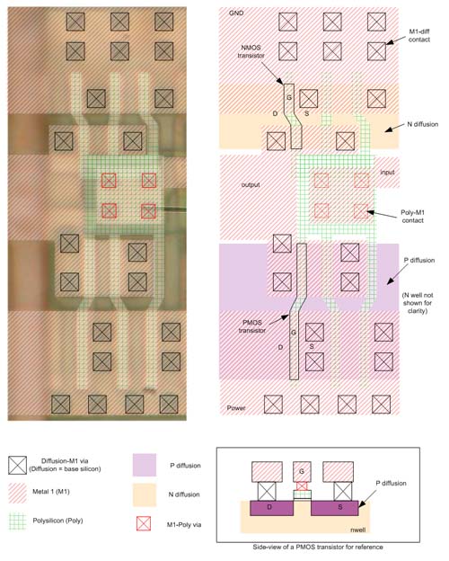
Already, we have correct answers (and winners!) for Name that Ware May 2006, which is really excellent! In order to help people with the more difficult ones, I am posting here an “answer key” for the “medium” ware.
This device is an inverter. The power is on the bottom of the image, and ground is on the top. As mentioned before, you can tell which side is power or ground because the PMOS transistors are larger (due to the inherent reduced mobility of holes, and therefore reduced saturation current per unit width, when compared to electrons). In a static CMOS circuit topology, the PMOS devices typically connect between power and the input/outputs; NMOS devices respectively go to ground.
This particular inverter is laid out as three NMOS and three PMOS transistors slaved together. This multiplies the current drive of the device by three. The reasons for putting devices in parallel instead of making them larger is many-fold. One big reason is that a standard “height” is used for all logic gates and flip flops in a design like this. If a device’s design calls for a gate width that violates the height rule, it has to be broken up into multiple parallel devices. Using a standard height enables automated place-and-route tools to easily drop logic cells side by side, like the movable type on an old-style printing press. Also, parallel devices have lower parasitics for certain key parameters (such as gate resistance), although at this technology node gate resistance probably is not a huge concern. It also occurred to me that it’s possible there is a fourth finger to the left on this circuit (computer people love powers of 2!), and it may just be hidden by the strap of metal 2 running on the left hand side.
You can also download the Visio file that I created to generate this answer key. The Visio file is useful in case you want to take one of the “hard” images and paste them into a new Visio file and use my color scheme as a template. Drawing simple polygons and text notes over an imported .JPG in Visio is a relatively easy way to do bookkeeping on what polygon goes where when trying to decode more complicated circuits.
Good luck, and hopefully people will find this an interesting challenge!

Very useful information. I think it is useful for many people. Thank you for your blogs.
interesting post hehe pretty informal check out destr0yed.com its a new hacking forum