Archive for September, 2007

Made in China: Craft

Tuesday, September 11th, 2007

I’d like to introduce you to a man who I know simply as “Master Chao”.
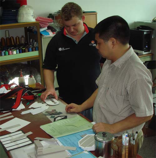
Master Chao is the person in the foreground; in the background is Joe Perrott, who you will see in many of the photos and videos I have from China. Joe is our excellent project engineer from PCH China Solutions. But I digress.

Why am I introducing you to Master Chao? Because I’m pretty sure you have used or seen something in your lifetime that was crafted by the Master. When I went to the sample room for this factory, I was shocked at how many items I saw on their shelf that I had myself purchased, used, or seen in a store in the US — top-tier consumer brands manufacture their stuff here — and to the best of my knowledge the factory has just one master pattern maker, and this is him. Indulge me with a moment of philosophy.

The advent of modern CAD tools have brought about a rather coarse attitude towards the arts and crafts. It used to be that the finest furniture was designed and built only with the intuition and skill of a master craftsman; now, we all go to Ikea and get our CAD-designed, supply chain managed, picture-book assembly furniture kits and despite all that it doesn’t look too shabby. As a result, the word “craft” has been relegated to describe some scrapbook or needlepoint kit you buy at Michaels and put together on a slow weekend. We’ve sort of forgotten that in an age before machines, “craft” was the only way that anything of any quality used to be built.

It turns out there are still things where Craft, and I use it with a capital “C” here, matters–it’s where CAD tools haven’t brought about the ability to simulate out our mistakes before we build them. The creation of a flat pattern for textile goods is a good example of a process that requires a Craftsman. A flat pattern is the set of 2-D shapes used to guide the cutting of fabrics. These 2-D shapes are cut, folded and sewn into a complex 3-D shape. Mapping the projection of an arbitrary 3-D shape onto a 2-D surface with minimal waste area between the pieces is hard enough; the fact that the material stretches and distorts, sometimes in an anisotropic fashion, and the fact that sewing requires ample tolerances for good yields makes it a difficult problem to automate. On the chumby, we add another level of complexity, because we sew a piece of leather onto a soft plastic frame. As you sew the leather on, the frame will distort slightly and stretch the leather out, creating a sewing bias dependent upon the direction and rate of sewing. This force is captured in the seams and contributes to the final shape of the device. I challenge someone to make a computer simulation tool that can accurately capture those forces and predict how a device will look at the end of the day.

Yet, somehow, Master Chao’s proficiency in the art of pattern making enables him to very quickly, and in very few iterations, create and tweak a pattern that compensates for all of this. It’s astounding how clever and how insightful the results can be. And really, the point of this particular post is to introduce you to a person whose old-world skills — absent computers, all done with cardboard, scissors and pencils — has likely played a role in the production of something that you have used or benefited from in the course of your life.
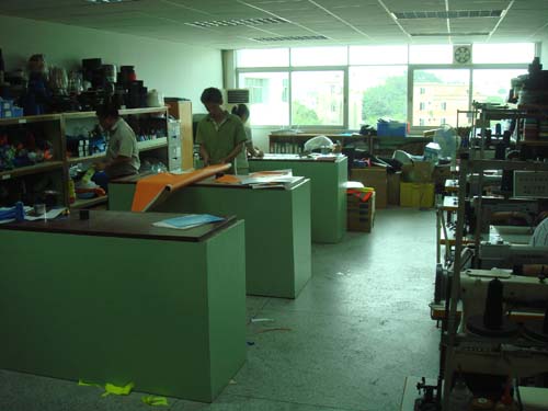
Not a single computer in this office, yet the products developed here wrap around a wide array of high-tech products.

Nintendo DS vs Girl

Monday, September 10th, 2007

DS 1, Girl 0. Poor Rachel, surrounded by such nerds.

And poor me, I lost that round of Tetris to caustik. And the next round. And the next round…

Winner of Name that Ware July 2007

Thursday, September 6th, 2007

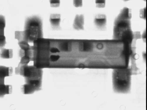
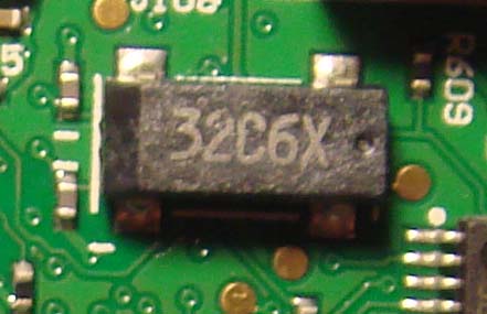
The Ware for July 2007 was indeed a pair of crystal devices. The top image is an SMT crystal oscillator. It embeds both a quartz crystal and some active circuitry to create an autonomous CMOS-level frequency reference. The bottom image is of a “tuning fork” quartz crystal–you can see the mounting for the tuning fork structure in the X-ray–and it is a passive device that requires an external chip to cause it to oscillate.

The bottom device is actually a sort of “trick question”. Nobody got it exactly right! The interesting thing about the bottom image is what it looks like in visible light:

Compare it to the X-ray:

You may ask, what is going on? Well, the X-ray goes right through the plastic, so you don’t see it in the lower image. Instead, you see the shadows of a classic “metal can” oscillator. Why would someone go through the trouble of burying a metal can in a rectangular plastic case? The reason the overmolding is done is to allow the part to be machine-assembleable. The round can normally used for these watch crystal oscillators are difficult for machines to pick up and place, whereas a flat plastic surface with four pads is much more amenable to the vacuum tweezers used for automated assembly.

Participants in the contest could have called it out as an overmolded device because you can see the dark shadows of the four pads used to tack the device to the board in the x-ray…well, at least none of us are radiologists trying to diagnose a patient, thankfully!

The winner for Name that Ware July 2007 is Hugo! Congrats, email me for your prize. This one was relatively easy to judge, thankfully. I’m of course behind on getting August’s up (my, it’s September already!) but I wanted to spend some time on the Made in China series before catching up on Name that Ware.

City Pictures from China

Thursday, September 6th, 2007

After going through the many photos I took in my travels over the past several months, I found two that I thought were interesting and shareable. Both images are clickable links to a higher-resolution version; and remember, all content on this website is Creative Commons by-nc-sa.

This photo is a nice juxtaposition of an artery of speeding humanity against the steel-and-glass body of Hong Kong that it nourishes. This was taken from the balcony of the China Club in Hong Kong. The China Club is a members-only affair, and we were fortunate to be there as guests of Liam Casey, aka “Mr. China”.

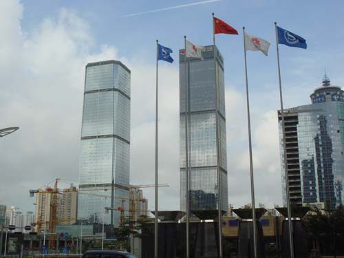
This was an unusually sunny day for Shenzhen; in honesty, it’s rare to see blue sky due to the pollution in the area, but for several days in a row during that trip there was beautiful weather. Shenzhen’s skyline is growing at a frenetic pace, and it’s a very planned city, as evidenced by the regularly arrayed skyscrapers–it’s almost as if the city planners played way too much Sim City in a previous life. Shenzhen city is slated to have a minimum of 40% “green areas” and so far they are doing a good job of keeping to that. The ever-present construction cranes in the foreground are an indication of the eternally under-construction look of the area. This picture was taken from the front of the new Sheraton Futian Sheraton, a hulking, obsidian black palace of a hotel, a gaudy icon of parvenu Shenzhen. Comfortable rooms, so-so food (but good food can be found in walking distance) and as always, free bottled water and free internet (a custom I wish US hotels would adopt!).

More Scope Pr0n

Thursday, September 6th, 2007

The Youscope demo is a hard act to follow up on, but I’ve had this scope screenshot for a while now and I thought it was so neat that I wanted to talk about it a bit on the blog.

Before I dive into the post, let me say that the best accessory I ever bought for my scope (a Tek TDS5104B–don’t let anyone ever tell you an Agilent is better than a Tek!) is the P6245 active probe. After suffering for many years with a Kikusui 100 MHz analog scope with second-hand passive probes, the quality of measurements I get with the active probe and the TDS5104B brings a tear to my eye. For the first time ever I can see traces that actually look like the darn SPICE simulations.

Here’s the background behind what we’re looking at in the screenshot. The top trace is the data line of a memory bus; the bottom line is the clock. The trigger is set on the data line–not the clock line as you’d expect. The test pattern being run is a repeated 0xFFFFFFFF-0x00000000 transition using four different bus drive strengths in sequence on the microprocessor. You can see each of the four drive strengths on the bottom clock trace, for example, at point “C”.

The particular bug this trace is supposed to capture is a ground bounce problem, as shown at point “B”. The rising transition “F” is what causes the ground bounce at “B” (note that the dip at “B” does not happen on anywhere else). The reason “F” trails the ground bounce event is because the cable of the passive probe used for the Data line has a fairly long delay–another measurement was used to calibrate out this fixed delay. The time difference of F – A approximates the delay differential between the active and the passive probes. You can also clearly see the rise time contrast between the two probes in this screen shot.

I think it is so cool that one can so clearly capture a problem as difficult to characterize as on-chip ground bounce using only conventional probes on external signals.

The other really neat thing about this set of scope traces is that it shows the timing of both the microprocessor->memory and the memory->microprocessor in a single shot. This is because I’m triggering off of the data line, not the clock line. On the data trace, you can clearly see the Processor-driven data trajectory (“D”) and the Memory-driven data trajectory (“E”). On the clock trace, you can see two phase-shifted versions of the clock. One of them is the clock timing relative to when the CPU drives the bus–this is G-F. The other one is the clock timing relative to when the Memory drives the bus–this is C-F (minus a clock period). So in a single picture, you can divine the available setup/hold margin in both directions of the bus!

You can also see other “good things” in the scope trace, such as the auxiliary measurements for frequency, amplitude, duty cycle, and rise time. You can also see how the clock trace is pretty well formed overall, with minimal over/undershoot, and you can get an idea of how much a passive scope probe introduces overshoot artifacts by contrasting it against the top trace. This picture is truly worthy of a thousand words!

OK, so I’m a real geek for getting so excited about a screen shot like this, but really, after teaching this sort of stuff for several years at MIT and then running countless simulations of chips to validate scenarios like this, it’s somehow very satisfying to be able to go into lab and actually see that the real world does match up with theory so nicely (even if it is a bug). If I ever teach digital design again, this shot is going into my slides and my problem sets.

And, yes, this was a problem found on the chumby DVT prototypes some months ago and it has since been resolved. This ground bounce, under certain conditions, would upset the internal clock multiplier of the CPU. The fix involved multiple improvements to the board layout, but in the end nothing can compensate for the relatively high inductance designed into the chip package. Therefore, the most important fix was to use a much higher clock frequency reference so the multiplication factor was only on the order of 20x instead of 10,000x (a 16 MHz reference instead of a 32.768 kHz reference). Reducing the period of ground-bounce noise integration by a factor of 500 resolved the stability problems of the internal VCO of the CPU’s clock multiplier PLL.