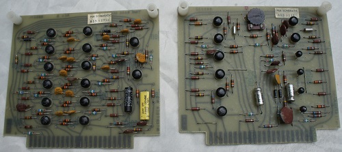
The ware for September 2012 is shown below.
Hopefully this will be a bit easier of a retro-ware than the previous month’s! I’ve included photos of all three circuit boards that I have from the ware. Again, this is one for which I have no idea what it is from, but have been curious about since childhood.


[…] Bunnie’s “Name that Ware” for September 2012. Hopefully this will be a bit easier of a retro-ware than the previous month’s! I’ve included photos of all three circuit boards that I have from the ware. Again, this is one for which I have no idea what it is from, but have been curious about since childhood. […]
It looks like they were made by Intertech Inc, and I’d guess from the 60’s or 70’s. One on the top right has the look of an oscillator and divider; the bottom one possibly a 4-bit register. I’d guess out of a terminal or tape drive.
Upper left board says “time base” and the lower one looks like it says “disp”, leading me more towards a terminal
This latest board looks like some kind of driver board for an incandescent bulb display. Lots of 100 and 330 ohm resistors for current limiting. With 17 transistors (probably) it could be some kind of hex display for a single decade. (1-F and decimal point). Or some kind of counter. Interesting stuff, I used to work on this kind of board in the Air Force. All three boards may be from the same unit, similar connector. Fun stuff, looks like my junk box.
Thanks,
Brad
I think its an octal bus transceiver, like a 74245. The extra transistor is an inverter.
I’m in complete agreement on the Intertech, Inc. mfr. And, while I can’t say for sure where these came from, I worked a lot of years in a nuclear power plant that went commercial in the mid 70s and these look a lot like what GE made for their rod-worth minimizer and rod position information system boards. Those boards were designed in the 60’s and produced in the early 70s.. and are still in use today at that same plant.
The IO count for the bottom board might support the octal bus transceiver theory, but there are a lot of diode on that board that may be part of additional logic. The upper left board has a much lower IO count, so it might be more interesting logic. And whatever could that pot on the upper right board be for? I have a vague memory of a board where smaller transistors were PNP, and the larger packages were NPN. Dunno why.
Rather than octal, it looks like there are 7 identical circuits (150R series resistors, 10K pullups) on the left, and 4 pairs of transistors on the right. They look like they are cross-coupled thru the disk caps, probably flip flops. Could it be an ASCII decoder? Latching XON/XOFF or something similar?
This is somewhat off-topic, but I have a friend who has (what appears to be) a very similar PCB.
http://i.imgur.com/bAnNz.jpg?1
The PCB above is supposedly a primitive flight control system for a U.S. Military missile developed in the late 1960’s, it was purchased at an auction in the United states sometime in the last 25 years and has been a prized object in his basement ever since. The similarities in components and layout caught my attention.
Um, no, sorry. No similarity at all.
D/A converters?
A155181 looks like a chain of flip-flops (= counter) on the right, and a wired-or (diode logic) decoder on the left, maybe decoding the flip flops’ states to eight individual lines. Reminds me a lot of the counters used in HP’s excellent 5245L counter. Could this board be used as the part of a shift register that moves along from 0…7 with each pulse on one clock input?
B155071B also looks like a bunch of similar flip-flops, maybe arranged as a counter or divider.
Or perhaps a four-bit decade counter, a diode-ROM, and drivers for a single seven-segment display?
Geez, I had some exactly like that years ago! Durned if I can remember what they came out of though. Maybe an old Burroughs tape drive?
I am thinking a buffer board for audio to set gain or tone in a pre-amp or amplifier.
Looks like driver boards out of an old alarm panel. Used to drive the lamps and relays.
Does the backside of the PCB give any clues?
It would certainly make it easier to read the text, and would make it easier to trace the circuit
It looks like it could be the world’s least fun NES game.