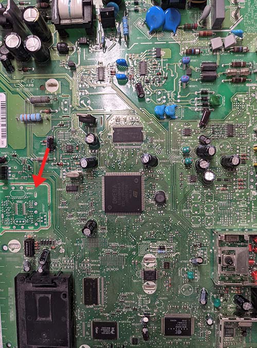
The Ware for August 2021 is shown below.
This months ware is probably a pretty easy guess. To make things a bit more interesting, the prize will go to the entry that has the most feasible (or the most entertaining!) theory as to the purpose for the tiny break-away, stand-alone PCB is on the left hand side, as indicated by the red arrow. The cropping just barely obscures the edge of the PCB, but basically there are three mouse bites on the edges that retain the sub-assembly PCB, so it could be sheared off and turned into a separate item. I always pay extra attention to blank spots like this PCBs, because they are riddles into some aspect of a product’s design or supply chain: someone put the effort in to design a thing — but then decided not to use it. This PCB has a lot of blank spots, but this is the only one that could be readily sheared off into a separate assembly.
This ware is also a guest ware, courtesy of “JeffA”. Thanks for the submission!

ICs include “Complete Broadband Satellite Front-End Solution” and the ST15518 does MPEG decoding and PAL/NTSC encoding.
Is it the Daewoo DSD-9280M Digital Satellite Receiver?
Perhaps the breakaway board is for a remote controller interface.
Probably the designer expected to make a calibration board for a small part of the complete design. Probably to test capacitors combination or some similar. Or only is there because to save money and the small board is for another product. I vote for my first option and the designer forgot remove it from gerbers.
This appears to be the schematic, for a container stacking forklift?? https://www.scribd.com/document/174300349/DRD420
That PCB looks to be an RF remote.
It looks like a phone line interface circuit. Probably on a cutout to prevent POTS voltages and signals from effecting the rest of the board. Might also be that way to ease regulatory approval.
Ok seems like a satellite receiver, model appears to be “GLA2” (possibly DXD416RD ?) by directv but I only can find reference to that in Venezuala..
Small board is an RF remote control.
So I posted a link earlier to what I believe is the schematic, and it seems to have been deleted. Was it spam filtered, or do you consider that a spoiler that shouldn’t be shared?
Auto-spam filtered, schematics are perfectly fine and totally welcome. Most links require a manual approval, if you only saw the number of pr0n/spam links I have to reject, you’d understand why.
The ware itself is almost certainly a standard-definition satellite set-top box (DVB-S / ISDB-S / DSS). The cutout part seems to be an optional controller for a front display that some SKUs of the box might have had, while others did not.
I agree with KeyJ; but it looks to be a DSI87 set-top box with the optional tuner controller removed maybe?
Eben is rigth.
Googling “j33103 y33101 u33101” you could find the schematics he pointed out, that match perfectly the board.
In the schematic, looking for U33101, leads you to the rf remote control schematic of the breakout, and the j33103 connector also matches.
It’s interesting. In the pdf there is a lot of notes about the board repair in spanish.
I think that the product is RCA DRD420RE satellite receiver:
https://www.manualslib.com/manual/313361/Rca-Drd420re.html
https://www.ebay.com/itm/273513146966?hash=item3faea76a56:g:K-wAAOSwDrpbx58H
My guess would be that it using fact the optional remote for the settop (note the slots for a shield can) …. I’d guess that it’s on the same board so that both the board and remote can be programmed with a unique code on the same manufacturing jig
The small board is the receiver for the RF remote control that came with the higher end models. It isn’t a remote control itself as it has no buttons and uses a KESRX01 ASK receiver chip.
It snaps out to mount behind the plastic fascia.
Presumably it was cheaper to make it all in one go than to do an additional run of just the receiver.