This entry was posted on Friday, August 16th, 2024 at 6:54 am and is filed under name that ware. You can follow any responses to this entry through the RSS 2.0 feed.
You can leave a response, or trackback from your own site.
I’m not an electronics pro by any stretch of the imagination, but here are my notes.
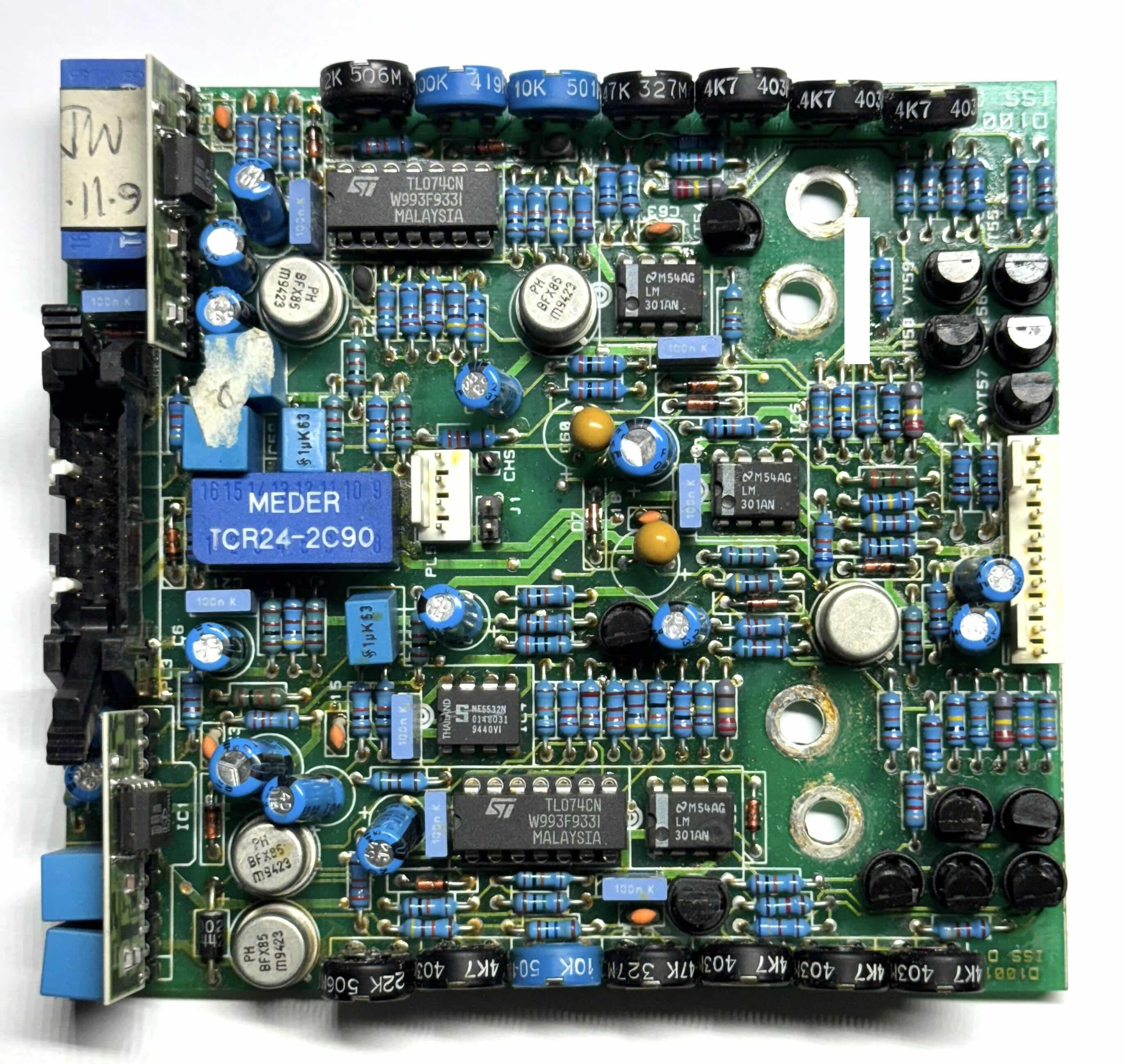
The board looks pretty much entirely analog, with some level of symmetry between the top and the bottom. Dual channel something? Or differential something?
That blue MEDER component could be a 24V DPDT reed relay? There seems to be another identical one on the top left corner, on the left of the daughter board.
Talking about daughter boards, not sure why they would use them. Form factor constraints? Modularity?
The 4-pin connector in the middle could be some kind of additional low power supply.
I’d say this is a somewhat old industrial board, maybe power-sensing or fault-detection related?
The daughter boards are hybrid microcircuits (ceramic PCB, silkscreened resistors). (Though I don’t know why there is a big old DIP8 in there.) They would very likely be off-the-shelf components from another manufacturer.
I’m putting my money on “two-channel galvo driver”, because anything with two channels, analog circuitry, and a bunch of tuning potentiometers looks like a galvo driver to me
(this may be a personal problem)
The 4-pin connector in the middle next to a relay could be the laser output.
The big latching connector made me immediately think motor controller for some reason. I used the OSMC (Open Source Motor Controller; https://robotpower.com/products/osmc_info.html) a long time ago that had the same connector used with a ribbon cable. The dual channels could be for a two-wheel or two-axis robot.
All of the potentiometers, opamps, and passives could be an analog control circuit, maybe a PID with 3 adjustments for gains, 3 for filter cutoffs, and 1 for I-term saturation (with the transistor).
One reason I have seen to mount small daughter boards like that is for 1-axis sensors, for example accelerometers, gyroscopes, or magnetometers. But it might be strange to mount those on a noisy motor controller, so I don’t know.
The two pairs of large through holes could be screw terminals for DC motors, but those transistors don’t look like beefy enough to drive a lot of power, and then there wouldn’t be a place for power input. So maybe I am way off base.
Two four-channel amplifiers with a two-channel amplifier in the middle, an astonishingly-silly amount of resistors and a general sense of low-volume production from the wonky caps and solder.
These and the silkscreen hint “ISS” on the outer corners makes me think that it’s a part of a “high-end” home audio amp, *possibly* of the sort that is assembled at home by people who have a strong belief in the magical power of gold-plated connectors on digital interfaces.
I doubt that its “high-end” audio, given that its using jelly bean op amps and lots of trim pots. The BFX85 transistors are 1A rated, so the board must be driving something with significant current requirement. Lots of resistors and few caps, so it doesn’t look like active filters.
I think this is a board out of a Eurorack synthesizer module. The 16 pin ribbon cable connector even has the fat +12v and ground traces routed near the correct pins. The ceramic SIP modules are interesting; they might be some function that needs laser trimmed resistors matched or in ratio, like instrumentation amplifiers. I puzzled over the four big holes for awhile; they seem to be the mechanical mounting, but also appear to have traces connected on the back of the board. Maybe just power between this board and another one. Not sure what the module function might be, but I’ll guess it is a dual VCO. Those often have multiple trims for scale, offset, etc, which would explain the many trimpots.
It is a board from a Control Techniques (/KTK /Anyspeed ltd.) motor drive, now know as Nidec Control Techniques Ltd.
Probably designed in the late 70s until mid 80s, before they switched to SMD parts and started using digital controllers. Datecode on the TL074 is 1993wk31, but it is not uncommon for these kind of electronics to have long lifecycles of 10/20+ years.
As for the exact function of the board, is most likely is the controller keeping track of things (speed/torque feedback, either from a mechanical sensor or V/F/I sensing) and applying the required PI(D) loops and ramp/rate limiter. A lot of potmeters to adjust the relevant settings. Note: It appears to be two identical channels on first glance, but they have minor differences (like one loop for speed, one for torque for example), with some cross-over to eventually control one motor.
Relays are most likely for some small auxilary signals, run a fan (most drives are air-cooled) or something like that.
Most interesting would be to have a close-up of the hybrids on the left side. Not enough pixels there to figure out what those DIP8 chips are :)
I’m not an electronics pro by any stretch of the imagination, but here are my notes.
The board looks pretty much entirely analog, with some level of symmetry between the top and the bottom. Dual channel something? Or differential something?
That blue MEDER component could be a 24V DPDT reed relay? There seems to be another identical one on the top left corner, on the left of the daughter board.
Talking about daughter boards, not sure why they would use them. Form factor constraints? Modularity?
The 4-pin connector in the middle could be some kind of additional low power supply.
I’d say this is a somewhat old industrial board, maybe power-sensing or fault-detection related?
The daughter boards are hybrid microcircuits (ceramic PCB, silkscreened resistors). (Though I don’t know why there is a big old DIP8 in there.) They would very likely be off-the-shelf components from another manufacturer.
I’m putting my money on “two-channel galvo driver”, because anything with two channels, analog circuitry, and a bunch of tuning potentiometers looks like a galvo driver to me
(this may be a personal problem)
The 4-pin connector in the middle next to a relay could be the laser output.
I’m also just an electronics hobbyist.
The big latching connector made me immediately think motor controller for some reason. I used the OSMC (Open Source Motor Controller; https://robotpower.com/products/osmc_info.html) a long time ago that had the same connector used with a ribbon cable. The dual channels could be for a two-wheel or two-axis robot.
All of the potentiometers, opamps, and passives could be an analog control circuit, maybe a PID with 3 adjustments for gains, 3 for filter cutoffs, and 1 for I-term saturation (with the transistor).
One reason I have seen to mount small daughter boards like that is for 1-axis sensors, for example accelerometers, gyroscopes, or magnetometers. But it might be strange to mount those on a noisy motor controller, so I don’t know.
The two pairs of large through holes could be screw terminals for DC motors, but those transistors don’t look like beefy enough to drive a lot of power, and then there wouldn’t be a place for power input. So maybe I am way off base.
I searched for the “ISS” seen on the corners of the board and found this “Intelligent Spindle Speed” control board: https://www.candcnc.com/store-home/iss-05-intelligent-spindle-speed-control/ . Maybe this is something similar.
Two four-channel amplifiers with a two-channel amplifier in the middle, an astonishingly-silly amount of resistors and a general sense of low-volume production from the wonky caps and solder.
These and the silkscreen hint “ISS” on the outer corners makes me think that it’s a part of a “high-end” home audio amp, *possibly* of the sort that is assembled at home by people who have a strong belief in the magical power of gold-plated connectors on digital interfaces.
I doubt that its “high-end” audio, given that its using jelly bean op amps and lots of trim pots. The BFX85 transistors are 1A rated, so the board must be driving something with significant current requirement. Lots of resistors and few caps, so it doesn’t look like active filters.
I put ‘high-end’ in quotes on purpose; people who buy that stuff also buy gold-plated USB connectors. It’s not primarily a fact-based industry :)
I think this is a board out of a Eurorack synthesizer module. The 16 pin ribbon cable connector even has the fat +12v and ground traces routed near the correct pins. The ceramic SIP modules are interesting; they might be some function that needs laser trimmed resistors matched or in ratio, like instrumentation amplifiers. I puzzled over the four big holes for awhile; they seem to be the mechanical mounting, but also appear to have traces connected on the back of the board. Maybe just power between this board and another one. Not sure what the module function might be, but I’ll guess it is a dual VCO. Those often have multiple trims for scale, offset, etc, which would explain the many trimpots.
It is a board from a Control Techniques (/KTK /Anyspeed ltd.) motor drive, now know as Nidec Control Techniques Ltd.
Probably designed in the late 70s until mid 80s, before they switched to SMD parts and started using digital controllers. Datecode on the TL074 is 1993wk31, but it is not uncommon for these kind of electronics to have long lifecycles of 10/20+ years.
As for the exact function of the board, is most likely is the controller keeping track of things (speed/torque feedback, either from a mechanical sensor or V/F/I sensing) and applying the required PI(D) loops and ramp/rate limiter. A lot of potmeters to adjust the relevant settings. Note: It appears to be two identical channels on first glance, but they have minor differences (like one loop for speed, one for torque for example), with some cross-over to eventually control one motor.
Relays are most likely for some small auxilary signals, run a fan (most drives are air-cooled) or something like that.
Most interesting would be to have a close-up of the hybrids on the left side. Not enough pixels there to figure out what those DIP8 chips are :)
There are enough pixels to recognise the National Semiconductor logo. I’ll guess those are opamps.
Looks more like Philips, the logo.