The Wares for September 2010 are shown below.
Ware A:

Ware B:

So I’ve decided to mix up the format a bit: instead of photographing the entire body of an obscure ware, I’m going to try for the next couple of months to show a photo of a magnified portion of a very common ware. The challenge is to figure out what is the type or function of the common ware that this magnified portion belongs to. The photographed regions are all picked so that a reasonably specific and correct solution can be derived if you are paying attention to all the details.
Because I don’t know how hard this will be, I’ve decided to include two photos this time of completely unrelated wares, just in case one is totally unguessable, or if one is just way too trivial. This complicates judging a bit, but basically someone who can guess both will be picked over someone who can just guess one.
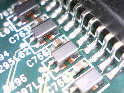
The first one has 4 differential pairs coupled via inductors to a chip. My guess is that these are connections between a PHY and jack for 1000BASE-T.
I think that may not be a chip, but a connector on the first; my guess is a LVDS-type video interface.
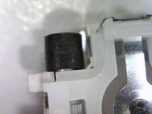
The second one might be the end of a D-sub connector?
The second one looks like the trackball mechanism from a BlackBerry/smartphone. The metal tongue allows an SMT switch to be triggered by pressure on the ball itself, while that black cylinder sits over top of what I believe is a hall effect sensor and tracks rotation along a single axis.
For reference: http://images.channeladvisor.com/Sell/SSProfiles/42000180/Images/3/Blackberry_8800_Trackball.jpg
A clock comes to mind for the second one (garden variety quartz clockwork from any random wall clock, or similar) – they tend to have little cylindrical black magnetic rotors for the main motor (flipping 180° per second), and there’s a gear at the bottom. The circular thing could be the terminal for a single AA battery, as is typical.
The construction doesn’t quite fit what I’d expect from a clock though: usually they’re more horizontally laid out than vertical, and it would be missing at least one of the poles next to the rotor (unless that has simply been disassembled). But maybe we’re seeing the whole thing from the side, and this particular model just has the rotor near one corner.
As for the top ware, it looks like differential pairs leading to a magnetics module for Ethernet (either 1000BASE-T or 2x100BASE-T). However, I’ve never seen those small inductors before (they’re clearly not the magnetics, way too small). I think the “IC” is the magnetics – it looks like it has wider pin spacing, more typical of these modules than of an IC. I’ve never looked at a datasheet of a magnetics module in detail, but I’m going to guess that the pins between pairs leading to capacitors to GND are the center taps, to capacitively couple the midpoint voltage to 0V (or maybe to some reference voltage?).
Yeah, totally off base. It’s a blackberry trackball, as Garret said. http://static.sparkfun.com/images/products/09308-3.jpg
Ware A: Hall effect sensors? So the trackball idea looks correct to me.
The “inductors” in the first picture are actually small common mode chokes – these attenuate the common mode signals (which tend to cause unwanted radiation), while letting differential signals pass through mostly untouched.
Also, the big device behind looks like a set of 4 transformers in one small package – gigabit ethernet seems as a good a guess as any, as it uses all four pairs, though often these tranformers and chokes are now included in the socket itself. As mentioned before, the capacitors are likely to be going to the center taps of these transformers. If not gigabit ethernet, then another differential communications standard that requires galvanic isolation and impedance matching, e.g. 4 T1 transmit pairs.
As for the second picture, part of it looks like a button cell holder, possibly out of a childrens toy or a clock.
The second one is from a blackberry scroll ball thing. The black roller on the end spins when the ball is rolled in 1 of the four cardinal directions (does not roll backwards). Under it, a small hall effect sensor is placed to detect the rotation. The metal tab on the right is a spring for the “clicky” feel of the ball.
The first picture I’m less sure of, but it looks like Ethernet. The 4 paired inductors correspond with the 4 twisted pairs on an ethernet line. However, I generally thought that they were generally placed closer to the jack, rather than the IC.
Ware A is an LCD panel. Pins 20 to 30 of the 30 pin connector are shown. Common mode chokes on the LVDS data lines.
The guys who answered blackberry trackball for the second one are right, there are a bunch of pictures floating around on the net of the mechanism.
For Ware A I’ll throw USB into the round.
To me the black device look like the host controller chip, not some sort of plug. However I’d place coils close to a plug, not close to the host controller…
Could be LVDS as well.
As for naming the ware I don’t open enough popular devices to be able to recognize it.
I believe the first ware to be the PCB of an LCD TV.
The PCB layout, solder pads, and even the color of the PCB itself reminds me a lot of the PCBs found in LCD television sets.
And like everyone else has already mentioned the chokes and capacitors make me think balanced pairs for LVDS for connection to an LCD panel.
The first picture could be a 4-lane SAS connector. So it could be either a SAS controller or a SAS drive.
[…] bunnie’s blog Tags: 2010, Name, September, Ware Posted in Game Development […]