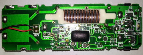
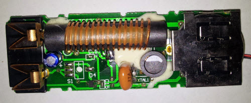
The Ware for May 2014 is shown below.


Thanks to @jamoross from Safecast for contributing this ware!
This entry was posted on Sunday, May 25th, 2014 at 4:07 pm and is filed under Hacking. You can follow any responses to this entry through the RSS 2.0 feed.
Both comments and pings are currently closed.
Looks like a WWV receiver or similar?
Upon further reflection, I don’t think these are two sides of the same board, as I initially thought. Instead they are two separate boards, perhaps a matched pair (note square corners in right of lower image). That communicate with a 10 MHz (or whatever) radio signal.
Perhaps some sort of remote alarm for some condition. Be it temperature, radiation, water, etc.?
I think they are the same board. The square corner is an illusion caused by the angle from the underside. It’s a metal bracket and the notched corner of the PCB is obscured behind it, as it stands out from the board. A photo taken at a close range will cause that. It’s just the PCB flipped horizontally rather than vertically.
I’m betting it’s a WWVB, WWV, or similar receiver.
It does look like a receiver of sorts (like the time signals mentioned), but it doesn’t really have any useful *outputs* for being a time receiver. “BZ1” could be a buzzer, so alarm clock, but there’s no time display that I can see nor any user inputs.
Maybe it’s just meant to receive some alarm signal? Like an older style “key finder” type thing (or maybe that antenna is actually BT-LE capable, but the device seems too big for that)
The antenna looks pretty similiar to a garage door opener I’ve recently seen.
Without knowing what kind if in- or output device is connected to the cable it’s hard to guess.
I wonder about the connector to the left in the second picture. It looks vaguely like the connectors used for thermocouples, so maybe this is part of a wireless temperature sensor? BZ1 sure sounds like it refers to a buzzer, so maybe it’s got a programmable threshold alarm warning function or something.
Strange device. There is the BZ1 connector. I guess the device off-photo is a piezo buzzer. Then there is a led. So it can blink and beep and has a battery. Note the two-pin connector on the left. Obviously this device is intended to be plugged into something with two pins.
As people already have said the coil indicates a radio receiver of lower frequencies. Time signals is one of the applications that comes to mind.
So from the board itself there is not a lot of clues, except the obvious low cost manufacturing look of it.
I tried to extract some info about the nature from “Thanks to @jamoross from Safecast”. Googling for safecast turns out Radiation moitoring, a weather station web-store and a copy protection scheme. This seems to be to cheap for radiation monitoring. My second thought was some kind of weather station add-on (timing receiver), but it seems a bit strange with the buzzer and separate battery. Wouldn’t that be included in the weather station from the start?
This leaves the copy protection scheme. Then this would be a hardware lock that provides the encryption key. This could possibly be something that changes depending on what time it is.
Here are my guesses…
John Hawkinson: They are absolutely the same PCB, rescale them, flip one, they perfectly line up, with vias and through-hole components.
It reminds me of a “remote doorbell-type” of transmitter.
On the “bottom” picture, there’s a coin-battery holder on one side, and a larger two-pin connector on the other side. There’s also an unpopulated footprint labeled S1 (“Switch”?), with four pads (one right, three left, two of each are connected). It’s parallel to the “large two pin connector”, so my guess is that this connects to a bigger push-button in the same device.
The XTAL has two possible footprints, the one currently fitted looks like a cheap “ceramic resonator” part -> cheap!
There’s a single LED on the right hand side of the “top” led (LD1) and the only meaningful connection going into the whole “chicken food” area to me seems to be the trace from the IC1 (black blob) via C6 and R6 to Q2. Q2 probably switches Vcc to the rest of the chicken-food.
My guess is that this comprises a CW oscillator/”power amplifier” feeding the magnetic antenna. (Q1 pulls down the net going via C3, C2, C4 to the non-GND connection of the ferrite-core antenna). C2, C3, C4 are paralleled, so maybe this was tuned to get the precise frequency right combining several standard-value components. Also all these resistors/capacitors/… have low-numbered designators, I think whoever put together the circuit occupied itself with this part of the schematic first, probably this was the most tricky to get right good enough and most important: *cheaply*…
Why do I think that this is a transmission antenna in the first place? Because all the timing receivers you see (WWV or german DCF77) use a very high-Q tuned LC circuit with many, many thin loops of wire, instead of the dozen rather big loops in the given circuit.
So, to summarize: It’s the PCB found into a remote-controlled dorbell, the outside part. When you push the button (connected to the large-two-bin connector, it’s a separate part inside the housing of the doorbell-knob) the LED lights, the buzzer gives audible feedback to the person ringing the bell, and IC1 pulses the transmitter encoding some information for the door inside to ring.
Here are my annotations on a picture:
https://docs.google.com/file/d/0BxaUhDCUXNJCNnVkNENvS0ZDNzQ/edit?pli=1
“paint.net” file, with layers, rescaled:
https://drive.google.com/file/d/0BxaUhDCUXNJCdjE5bXRQOS1CeGc/edit?usp=sharing
My guess: some kind of anti-shoplifting tag, the kind where the product is wrapped in a cable that if cut, an alarm is triggered. The piezo (BZ1) is for the local alarm, the antenna is to either (or both) trigger it when the device passes through the electronic fence at the shop door, or to trigger a central shop alarm when the cable is cut. The 2-prong connector to the left is for the cable. Something like this: http://www.wellguardcn.com/china-eas_spider_hard_alarm_security_tag_for_supermarket_anti_theft-1813592.html
An electronic dog collar?
Well, Safecast seems to point me towards thinking this being a personal radiation detector. Perhaps the coiled device is a geiger counter of some sort, and the wires point to an alarm if the radiation level gets too high.
Just looking at the thing, though, it looks like a device used with a home alarm system (like an intrusion detector – the coil wirelessly connects to the home unit and the wires would go to a open/close detector device).
My completely off the wall guess is an old school pager
it could the *receiving* part of a radiation alert system, using a low frequency band similar to timekeeping stations.
When some radiation is detected by one or more detectors, the detectors could broadcast some signal to receiver devices like this one (either directly or via repeaters/base stations), in order to alert the population that something is wrong.
Similar to what f4grx said, it’s definitely a radio receiver for likely an alert system. The frequency used is around 1 to 3 MHz, for a fixed frequency band. Minor frequency tuning is done via D1. There’s a microcontroller running off 12Mhz resonator, so the alert signal should be coded. The 2 copper contact allows insertion of some device into this or vice versa.
Bz1 is piezo driven via the micro boosted by the inductor.
Wireless humidity sensor ?
Looks like a portable radio.BZ1 could be the internal speaker,although why it is buzzer-labeled I do not know.
Furthermore,either it has no headphone socket and takes rechargeable batteries or that is one odd headphone socket.
AM/FM portable radio
It should be a restaurant pager (sometimes called a ‘site pager’).
One of the clues is that two pin connector on the bottom – that’s the type that restaurant pagers use, and it’s intended for high cycles, robust performance, and untrained staff.
The BZ1 buzzer might be a peizo buzzer, but the traces are the same width as the power traces. Peizos are super low power. In addition, it looks to be on the same circuit as the “grey disk”, which I suspect is actually a peizo sounder. The off board BZ1 could be a vibrating motor, which works best attached to the case, not to the circuit board.
Use of these is super simple – unplug from the dock and hand it to the customer. The number is written permanently on the case, so no display is needed. The dock often has dedicated buttons for each pager. To signal the customer, push the matching button.
The LED, being located down near the battery, seems more likely to be a status indicator. I could see the alert LEDs being wired into the vibrator, since they are case mounted. Some of these devices are absolutely festooned with LEDs on all sides, but that and the vibrator make sense when you realize they can be used in environments like bars and clubs, where high ambient noise can be quite common.
Loop Powered Field Instrument with HART Interface (Highway Addressable Remote Transducer).
Antenna could be for monitoring EMF.
An electronic ‘stud finder’ and/or (they’re often combined) a detector for AC power running in walls? Could the copper connectors on the left be simple continuity test points for mains fuses?
lightening detector
Some kind of monitoring device with its own battery backup and what looks like a receiver must be a transmitter?
Does it monitor mains ac and will sound an alarm/send out an rf signal if there’s a power outtage? That’s a tricky little sucker.
Perhaps some other kind of alert system for deaf folks, eg for tsunamis or chemical spills? The wires would go to a vibe motor.
Or, combining some of the above ideas, it could be a site-specific alert buzzer. Eg, inside a reactor, subway, ship, or mine there would not be a reliable way to receive phone alerts to an emergency. A low-frequency coded signal would punch through a lot of mass. This would assume that the connector is for recharging the battery when the user is off-shift.
The battery is a non-rechargeable, probably 3V lithium. For this reason, I don’t think the 2 big copper contacts are for recharging the device. Perhaps they are to read/program the device via some sort of 1-wire protocol or to get an electric shock out of it. My first option would be a restaurant pager, but this has been said already. The second option would be part of an electronic leash (to be installed on the dog collar end) and give an electric shock if the dog owner via the remote wants to control his dog, perhaps also if the dog barks too loud (sensed via a transducer connected to BZ1 leads)
Lithium battery so going for low weight device. Guessing it could be used as a tracker. For following migrating birds or animals. Low frequency winding suggests longer distance radio tracking ping rather then higher pager frequency bands.
I think you’re almost there – it could be a dog shock collar that detects a buried RF boundary wire and shocks the dog when they get too close
(as per this patent http://www.google.com/patents/US6269776)
The first stage of a 3-4 stage Explosive FLux compression device?