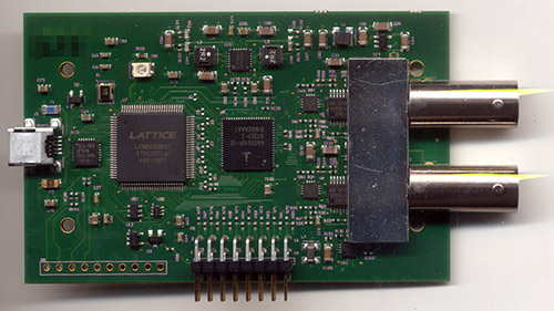
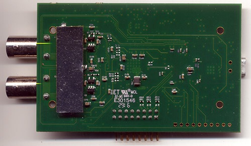
The Ware for November 2016 is shown below.


Happy holidays!
This entry was posted on Wednesday, November 30th, 2016 at 1:26 am and is filed under name that ware. You can follow any responses to this entry through the RSS 2.0 feed.
Both comments and pings are currently closed.
Thinwire ethernet?
USB ‘scope?
Duel A/D converter chip, and ‘glue logic’ chip. Either stereo recording, or USB scope
That’s a 10 bit ADC, unlikely its for audio recording. I think USB interface is full-speed only, guessing that’s maybe not enough bandwidth for any USB-based output, which suggests pins at bottom might be digital out.
Some sort of interface card from a modular data acquisition system?
2 Channel USB O-Scope, with some digital channels on the bottom?
It looks to me like an usp scope, definitely.
I’d go with a Synchrotech MSO 28 as the layout looks similar with the digital on the side…
I first wondered about the 2 GSa/s headline spec, given that the A/D converter is only 200 MSa/s.
But looking at the detailed specs, it’s “single shot: 200 MSa/s, repetitive mode: 2 GSa/s”, so I think we have a winner.
http://www.linkinstruments.com/mso28.html
You won.
http://www.anythingiwannawrite.com/2013/01/usb-hub-replacement.html
Link Instruments MSO-19?
http://www.linkinstruments.com/mso19.html
I think it is a network bridge to token ring.
Based on the dual A/D frontend with coax this is USB scope with logic analyzer capability (headers in the bottom). Together with Silabs USB IF this lead us to Sparkfuns USB Oscilloscope – MSO-28
(3G-)SDI converter board, probably used in a TV.
A Synchrotech MSO-28 2 channel oscope + logic analyzer
To those that keep saying Ethernet, note the USB micro connector at left.
Looks like WiMAX modem/prototype or SDR with similar frequencies and capabilities.
USB->FPGA->10 bit 2 channel ADC->opamps->antenna connectors
Look like this one was probably solved before I even got here. My first thought just looking at the board without even checking part functions was a USB digital scope. And it looks like the MSO-28 matches too close to be a coincidence.
But it seems strange that we see no memory chips for sample data. The Lattice part has no significant amount of RAM. Maybe they just stream all the data into the PC in real time and let the PC deal with it, but that would be difficult at the maximum sample rate claimed by the MSO-28. Strange…
The FPGA claims to have 28kBit of block ram, so with 8bit ADC resolution this allows you to store 3k samples. Ever worked on an old digital scope without zoom capabilities? The old Tektronix TDS had VGA resolution b/w LCDs, for example. You only could have 500pt on the screen at any given time, and store 2k samples or so.
http://www.tek.com/document/fact-sheet/tds-210-tds-220-fact-sheet
too easy this time :(, image googling KAD5610P-12 shows MSO-28 at the bottom of first screen
and image googling USB Oscilloscope MSO-28 pcb shows teardown of this unit ;-)
Two-channel USB oscilloscope with Lattice FPGA. Also, I guess the right angled headers are for the logic analyzer.