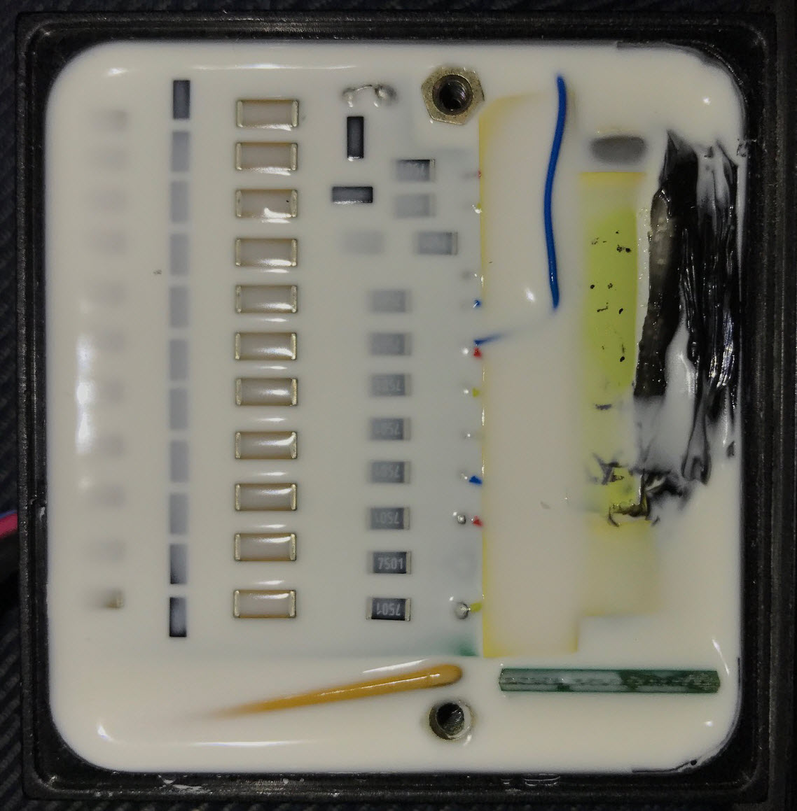
The Ware for July 2017 is shown below.

Decided to do this one with the potting on to make it a smidgen more challenging.
This entry was posted on Thursday, July 27th, 2017 at 12:17 pm and is filed under name that ware. You can follow any responses to this entry through the RSS 2.0 feed.
Both comments and pings are currently closed.

I’m tempted to say its a voltage multiplier circuit because of the array of capacitor, and on the left what looks like diodes.
Left part of the circuit looks like a charge pump indeed. Not that sure about the right part. My best guess – it’s LED, probably a HD44780 one, or not. Two wires on the left suggest that the entire circuit should be connected only to VCC and GND.
Also I see two holes for screws, so it seems that this circuit is designed to be mounted on a housing or some other flat surface. Also the circuit looks small, these holes are probably M3. I have no idea what this yellow wire on the bottom is. Maybe just a wire, or a thermocouple?
I suspect that this circuit was filled with something for a reason. If it’s an epoxy it suggests that the circuit should used outdoors. Also it could be some sort of heat conducting glue. I’ve used one recently and it has a similar color.
It could be just a voltmeter. Or a thermometer, probably designed to be placed close to the radiator.
those vertical black bars on the left look like SOT-23 transistors; the whole thing looks like a 12-channel driver board. The channels seem to be addressed individually by the coloured wires peeking through on the right. Not sure about the big yellow blob.
Good ‘ol white silicon potting. Looks very like a voltage multiplier on the left- vertical diodes and horizontal caps. Looks like they tap off of it with those 7.5K resistors. Multi HV supply?
I’d guess the thing on the bottom is a ~Gohm voltage divider to read off for feedback control. The Package on the bottom right might be a voltage controller.
You can see two wires coming in on the left. Got to be supply. HV-out would have beefier insulation. Output is probably on the bottom fed by whatever is in that black insulation/sleeve.
I do like metal inserts for screws, but brass right next to HV?
The yellow block on the right could be a transformer.
The base of a high-voltage toy from the Shenzhen markets? E.g. a tesla coil or Jacob’s ladder?
Looks like a BMS, probably for an ebike battery or similar.
I’ll go with Battery Management System for 12 cell LiPo battery, or some similar chemistry. Individual wires on the right going to different connections between cells, 12 resistors, one for each cell’s positive connection. Left hand side is probably caps and transistors balancing the cells. yellow thing in the bottom is a thermistor maybe?
Is there maybe a photomultiplier tube buried on the right hand side? The general architecture resembles
OK that didn’t work. One of these should.
https://mysite.du.edu/~etuttle/electron/circ371.gif
[img]https://mysite.du.edu/~etuttle/electron/circ371.gif[/img]
I would say the controller part for a LED lamp
white alu pcb, potting and yellow substance similar to remote phosphor scream AC driverless LED Module
the only problem with this theory is lack of visible LEDs, and those modules tend to be one side load
Yep. Looks like a Hamamatsu PMT with integrated HV.