The Ware for June 2018 is shown below.
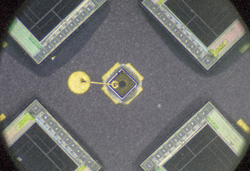
This month we’ll start with the very zoomed in and slightly torn down view of the ware, and if nobody’s nailed it I’ll release some more contextual images throughout the month.
Special thanks to Nava for giving me this ware!
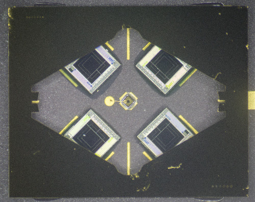
Update June 19, 2018: Looks like people are stumped by this one, so providing a little more context to see if anyone gets it…


It is definitely re-using the die from the TAOS (now part of ams) TLS250-series light-to-voltage optical sensors, but since it uses multiple of them I am guessing it’s one of their color-sensors with the filters removed.
Maybe a TCS34725 since it is easily available via Adafruit? :)
It is definitely an AMS (TAOS) optical sensor. Slightly strange to be using five dies but it is reusing TAOS a design so they must save some costs there. I think it might be a TMG4903 3D Gesture, Color, ALS, and proximity sensor module or at least from that family. Makes sense with north, south, east and west proximity and gesture sensors arranged as they are in the figure. The central die might be the IR sensor. Looks like a very interesting IC.
Link to that part is here: https://ams.com/tmg4903
That center item is almost certainly an LED die.
The four dies around the diode indicates that this is something (presumably a reflection) you compare that can move in X-Y directions either for sensing the movement or for compensating for it. Given that the “window” is black it is probably IR sensitive.
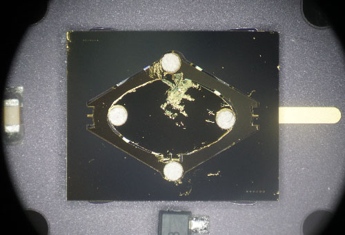
Looking at the last picture this is something that mounts in something round.
There can be a number of applications that come to mind. CD players use one of these although the size is probably a bit to large for this (I guess at around 10mm in diameter). There are also optical links that use the feedback for alignmant. Also interferometry comes to mind, especially since Nava, who supplied the ware, is working with that.
I would guess the sensor from an HP interferometer. No idea about the exact number though.
Cheers
That gold-wire bonded die in the center is def. a VCSL
https://www.gideonlabs.com/wp-content/uploads/2013/03/die-image-1.jpg
So since this is a laser plus four detectors around it i cant things of a “slow” application like gesture tracking. Maybe keeping something sort of plane accuratey parallel to another object. Or it’s some kind of 3D encoder which measures position + distance of an object.
I think this is a (fairly large) MEMS mirror with X-Y deflection. You can see the the X and Y hinges in the third photo (the outer ring pivots along the X axis, while the inner mirror pivots along the Y axis). The middle die is either an LED or a VCSEL, and is used for differential optical feedback with the four sensor dies around it providing +X+Y -X-Y -X+Y and +X-Y quadrant signals.
What we aren’t seeing is the motor part. Which leads me to believe it might be outside the part photographed – perhaps something interacting with the four silver dots (magnets?) from above, or perhaps patterned onto the mirror and hinges in a way we can’t immediately see, or on the underside. Given the non-symmetrical shape I also doubt this is completely general purpose, but it doesn’t look asymmetrical enough to be from a raster laser projector (those have a much faster X axis than Y axis). I’m going to go out on a limb and say this is for LIDAR applications.
Or it’s just a really bizarre 2-axis gyro.
For reference, here’s what the MEMS mirror from a laser picoprojector looks like:
https://mrcn.st/t/mems_picoprojector.jpg
Note the obvious Y-axis electromagnet patterned onto the support. I think this one uses magnetic Y deflection and electrostatic X deflection. Also, no feedback on this one, since it’s designed to be run at a fixed frequency and pattern and probably carefully calibrated for it (and designed to resonate at that frequency).
Yeah, okay, so Nava tweeted about this in January. Duh. It’s a TI TALP1000B:
http://www.ti.com/lit/ml/slbb089/slbb089.pdf
https://twitter.com/new299/status/953506843325693952
https://twitter.com/new299/status/953209172153085954
I’m guessing the oblong shape is to compensate the frequency response of the X and Y axes (since they’re nested).
130Hz resonant frequency is…. pretty terrible. I guess these are for slow, accurate beam steering. Laser show galvos resonate in like the 3 kHz range (good ones higher), and those are massive and built with conventional technology. I really wonder what this thing is intended for, really…
This tutorial from TI reads like a Hackaday post. Seriously, I think they have no idea what they want people to do with this.
https://datasheet.octopart.com/TALP1000B-Texas-Instruments-datasheet-10284605.pdf
The ‘schematic’ in the TI tutorial is also… a bit off. “Grd” instead of “Gnd”. The capacitor of 0.1 uF in the center of a loop(?). The Temp Sensor that is connected to Vdd using a point contact on one terminal, and via the above loop with the other connection.