“Pocketability” is the difference between Precursor and naked PCB FPGA development platforms. We hope Precursor’s pocketability helps bring more open hardware out of the lab and into everyday use. Thus, the mechanical design of Precursor is of similar importance to its electrical, software, and security design.
We always envisioned Precursor as a device that complements a smartphone. In fact, some of the earliest sketches had Precursor (then called Betrusted) designed into a smartphone’s protective case. In this arrangement, Precursor would tether to the phone via WiFi and the always-on LCD for Precursor could then be used to display static data, such as a shopping list or a QR code for a boarding pass, giving Precursor a bit of extra utility as a second screen that’s physically attached to your phone. However, there are too many types of smartphones out there to make “Precursor as a phone case” practical, so we realized it would make more sense to make Precursor a “stand-alone device”.
As such, we wanted Precursor to be unobtrusive and thin in order to lighten the burden of carrying a secondary security device. Our first-draft EVT design had Precursor at just 5.7 mm thick, placing it among the ranks of the thinnest phones. Unfortunately, the EVT device had no backlight on the LCD, which made it unusable in low-light conditions. Increasing the final thickness to 7.2 mm allowed us to introduce a backlight, while still being slimmer than every iPhone since the iPhone 8.
To minimize the thickness of Precursor, I first divided the design into major zones, such as the main electronics area, the battery compartment, the vibration motor, and the speaker. I then estimated the overall thickness of components in each zone and optimized the thickest one by either re-arranging components or making component substitutions until another zone dominated the overall thickness.
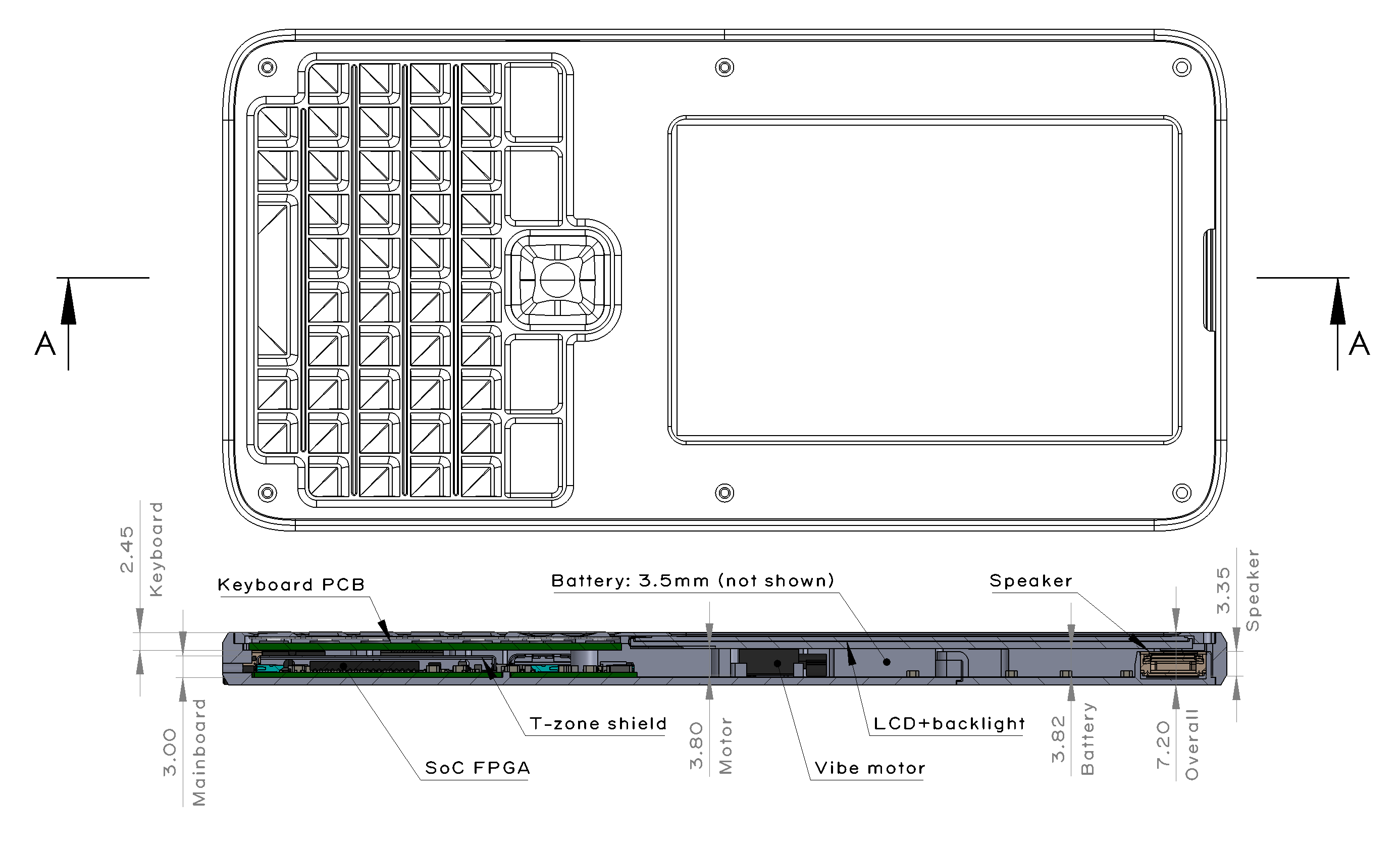
A cross-section view of the final Precursor design, calling out the dimensions of the various vertical height zones of the design.
After considering about a dozen or so mechanical layout scenarios, we arrived at the design shown above. Like every modern mobile device, when viewed by size and weight, Precursor is basically a battery attached to a display.
The practical limit on battery thickness is driven by the overhead of the protective wrapping around the battery. Lithium-polymer “pouch” batteries rapidly decline in energy density with decreasing thickness as the protective wrapper around the battery starts to factor appreciably into its overall thickness. The loss of energy density becomes appreciable below 3.5mm, and so this fixed the battery’s thickness at 3.5mm, plus about 0.2mm allowance for any swelling that might happen plus adhesive films.
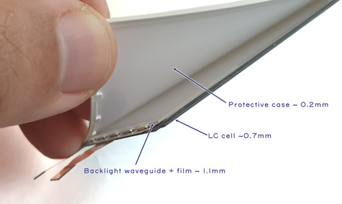
Teardown view of Precursor’s LCD with backlight attached. Note that to inspect the transistors inside the LCD, the backlight module needs to be removed.
Display thickness is limited by the thickness of the liquid crystal (LC) “cell”, plus backlight. Fortunately, LC cells are extremely thin, as they are basically just the glass sheets used to confine a microscopic layer of liquid crystal material, plus some polarizer films – in Precursor’s case, the LC cell is just 0.705mm thick. The backlight is substantially thicker, as it requires a waveguide plus a film stack that consists of two brightness enhancing films, a diffuser sheet, adhesives, and its own protective case to hold the assembly together, leading to a net thickness increase of roughly 1.3mm. The backlight itself is actually a full-custom assembly that we designed just for Precursor; it’s not available as an off-the-shelf part.
With the display and battery thicknesses defined, the final thickness of the product is determined by the material selection of the protective case. We use aluminum for the bottom case and FR-4 for the bezel (we discuss the bezel in a previous post).
Using aluminum for the bottom case allows us to shave about 1 mm (~15%) of thickness relative to using a polymer like ABS or PC at the expense of a fairly substantial increase in per-unit manufacturing costs. Although polymers are about twice the cost of aluminum by weight, an aluminum case costs about 10x as much to produce. This is because polymers can be molded in a matter of seconds, with very little waste material, whereas aluminum must be CNC’d out of a slab in a time-consuming process that scraps 80% of the original material. Surprisingly, the 10x cost-up isn’t the waste material; there is an efficient market for buying and recycling post-machining aluminum. Most of the extra cost is due to the labor required to machine the case which is orders of magnitude longer than the time required for injection molding.
Thus, while we could have made Precursor cheaper, we felt it would both be more pocketable, as well as more desirable, with the machined aluminum case: it would look more like a high-end mobile device, instead of a cheap plastic toy or remote control.
Using aluminum also allows us to play some fun tricks with the fit and finish of the product, thanks in part to the transformative effect Apple had on the mobile phone industry. Their adoption of CNC machining as a mass production process sparked a huge investment in CNC capability, making once-exotic processes more affordable for everyone. A good example of this is the single-crystal diamond cutting process for making shiny beveled edges. This used to be a fairly expensive specialty process, which you can read more about in this great thesis on “Precision and Techniques for Designing Precision Machines” by Layton Carter Hale which, on page 27, describes the Large Optics Diamond Turning Machine (LODTM). The LODTM relies on the raw precision achievable with a diamond bit to create geometries for mirrors without the need for post-polishing.
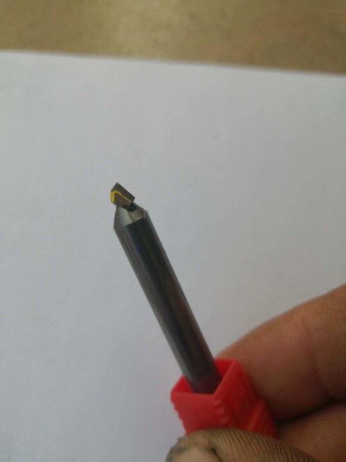
A single-crystal diamond bit, courtesy of Victor from Jiada
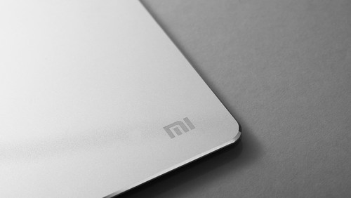
I first learned about this technique in 2017, when I brought a Xiaomi aluminum mouse pad with a mirror-finish bevel.
Despite a sub-$20 price tag, the mirror-finish bevel gave it quite an expensive look. Polishing to a mirror finish is a time consuming task, so I became curious about how this could be economical on a humble mouse pad. I bought another mouse pad, and brought it to Prof. Nadya Peek, and asked her how she thought it was fabricated. Readers who are familiar with our Novena laptop may recall her name as the designer of the Peek Array for mounting accessories inside the Novena. I’ve been lucky to have her mentorship and advice on all things mechanical engineering for many years now. So many of my products are better thanks to her!
She took one look at the bevel and immediately guessed it was cut by a single-crystal diamond bit, but she could do even better than making a guess. At the time, she was still a graduate student at the MIT Center for Bits and Atoms, where she had a Hitachi FlexSEM 1000 II equipped with the X-ray composition analysis option at her disposal. So, she took the mouse pad to the machine shop, chopped a corner off with a band saw, and loaded it into the SEM.
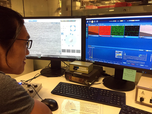
Viewing the output of the composition analysis.
If you zoom into the screen on the right, you can see the X-ray composition analysis reveals an unusually high amount of carbon on the aluminum surface (~10% by weight). Unlike iron, carbon is not commonly used in alloying aluminum. In this case, the chief alloying element seems to be magnesium, implying that the mousepad is probably a 5000-series alloy (perhaps 5005 or 5050). Given this, it seemed reasonable to conclude that the carbon residue on the beveled surface is direct evidence of a diamond cutting bit.
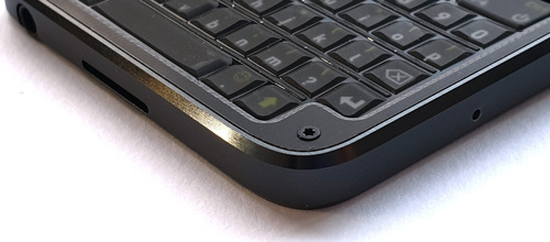
The shiny beveled edge on Precursor is brought to you by a single-crystal diamond milling bit.
Armed with this knowledge, I was able to work with Victor, the owner of Jiada – the primary CNC provider for Precursor – to specify a diamond-bit beveling process that brings you the nice edge finish on the final Precursor product. I also count Victor as one of my many mechanical design mentors; he’s one of those practicing-engineer-as-CEO types who has applied his extensive knowledge of mechanical engineering to open his own CNC and injection molding business. He always seems up for the challenge of developing new and interesting fabrication processes. That’s why I’ve been working closely with Victor to develop the campaign-only omakase version of Precursor.
Because Precursor’s case is CNC, we’re not limited to aluminum as the base material. It’s primarily a matter of cost and yield to manufacture with other materials. We could, for example, machine the case out of titanium, but the difficulty of machining titanium means we would likely have to machine two or three cases to yield a single one that passes all of our quality standards. This, combined with the high cost of raw titanium, would have added about a thousand dollars on to the final price of the omakase Precursor and we felt that would be just too expensive. Thus, Victor and I are currently evaluating two material candidates: one is physical vapor deposition (PVD)-finished stainless steel, the other is naval brass. These material choices were heavily influenced by Prof. Peek’s opinions. (It’s a coincidence the recently launched iPhone 12 uses PVD stainless steel for its case, as we have been working on this project since well before the details of iPhone 12 were publicly known.)
While both the PVD steel and naval brass are much more expensive than aluminum, they have a terrific hand feel and excellent machinability. Aesthetically, the main difference between the two is the color: for the stainless steel PVD, we’d be going with a high-gloss, polished black look, and for the naval brass we’re considering a brushed finish. The naval brass is more distinctive, but the soft metal is easy to scratch; a highly polished brass surface starts to look much less nice after a week or two of banging around in your pocket. A brushed finish hides such scratches and fingerprints better and over the course of years it should develop a handsome patina.
The major downside of the naval brass is that it’s highly conductive. Both the PVD stainless steel and anodized aluminum inherently have a tough, non-conductive surface layer; the naval brass does not. This is particularly concerning because if any of the internal battery connections get frayed, it could lead to a fire hazard. I’m currently working to see if I can find a surface coating that adequately protects the inside of the naval brass case from short circuits, but if I can’t find one, that may definitively rule out the naval brass option, leaving us with a PVD stainless steel case for the omakase version.
While good looks and a nice hand feel are significant benefits of going with a CNC process, another important reason I picked CNC over injection molding is anyone could build a full-custom version of a Precursor case in single quantities, with no compromise on finish quality or durability. Unlike the situation of injection molding versus 3D printing, which either use radically different base materials (for SLA 3D printing) or processes (for FDM 3D printing), your custom case can be made in single quantities with the exact same metal alloys and the exact same processes used in production Precursors.
This trait is particularly important for a mobile device and not just because the design works better when it’s built using its originally intended material system. It’s also because mobile devices don’t have a lot of extra space to devote to expansion headers and breakout boards. While it is beyond the level of a weekender hobby project to make a custom case, it’s probably within the scope of an undergraduate-level research project to undertake the necessary revisions to, for example, thicken the case and incorporate a novel medical sensor or a new kind of radio. In order to facilitate easier modifications to the case’s native Solidworks design file, I use a “master profile” to define the case body, bezel, and “ribbon” (the outer band that defines the height of the case). Helena Wang, another friend to whom I turn to for advice on mechanical design, taught me about the general technique of top-down modeling and using master profiles. Top-down modeling pushes a lot of design work into the up-front structure and planning of the 3D body in exchange for being able to revise the model without having to resolve dozens of conflicting downstream mechanical constraints. For example, when I realized I had to modify the case to be 1.5mm thicker to accommodate the backlight for the LCD, I was able to make the necessary change by just adjusting a single dimension in the ribbon height master profile, followed up by perhaps a half hour of cleaning up the offsets on structures which were defined outside of the master profile, such as the mounting points used to support the keyboard and the polymer radome that allows the WiFi signal out from the metal case.
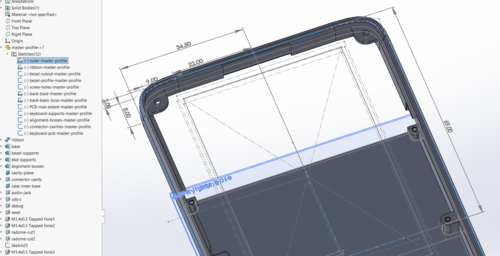
A screenshot of the CAD tool view of the Precursor case, highlighting the master profile that defines the outer dimensions of the case.
Of course, making edits to the master profile requires access to a copy of Solidworks, which is not an open source tool; but FreeCAD users are welcome to redraw the design in their native format! I’ve heard good things about FreeCAD, but I just haven’t had the time to learn a new design tool. For smaller modifications that don’t involve changing major dimensions of the case – such as adding some extra through-holes for sensors or internal mounts for additional circuit boards – the case design is also available in a tool-neutral STEP format. Every CAD tool I know of can accept STEP format and, since it is actually the format used for CNC fabrication, it’s by definition sufficient for creating copies of the case.
If you’ve read my posts over the years, you may have noticed that I’ve never taken a formal course on mechanical engineering. Everything I know has been either gleaned from taking things apart, touring factories, scouring the Internet, and perhaps most importantly receiving advice from friends and mentors like Nadya, Victor, and Helena. It’s been a wonderful journey learning how things are made, I hope posts like this and the associated design files will aid anyone who wants to learn about mechanical design, so they may have an easier time of it than I did. Most of all, I’m hoping applying my experience and making Precursor pocketable and hackable will enable more open source technology to make it out of the lab and into everyday use, without requiring anyone to learn about mechanical design.
Thanks again to all our backers for bringing us closer to our funding goal! At the time of posting, we’re just at 90% funded, but we’re also getting down to the last week to wrap things up. We need your support to get us over the 100% mark. We recognize that these are difficult, trying times for everyone, but even small $10 donations inch us toward a successful campaign. Perhaps more importantly, if you know someone who might be interested in Precursor, we’d appreciate your help in spreading the word and letting them know about our campaign. With your help, hopefully we’ll blow past our funding goal before the campaign ends, and we can begin the hard but enjoyable work of building and delivering the first run of Precursor devices.
I’m looking for a great company to create a new smartphone or either partner up with someone with an awesome idea.
Thank you!
Me too. Am into RISC-V SoC Smartphones.
I can partner with you
If I see a good post, you will not go without praising me, because every word written in the post you have written is very thoughtful, your way of writing is very beautiful and your views are also very good. This is a commendable post, as much as this post is praised, it is less, you should keep writing more beautiful posts in your life.
[…] See the entire design process post here. […]
Regarding the bevel cut:
I can’t give any information on how it is cut, but I can tell you that the presence of Carbon in the SEM says very little either way. Carbonaceous residues are wily and difficult to get rid of. Unless extraordinary measures are taken to clean a part and the SEM chamber prior to analysis, residual volatile organics will adsorb to the sample surface and polymerize under the electron beam. Because the carbon is on the surface (not suject to xray absorption) and the system assumes it’s buried, the matrix correction algorithms massively inflate the number.
Cleaning is typically performed using an RF plasma generator hooked up to a feedthrough on the SEM chamber.
Pick a piece of pure anything, clean it best you can with solvent, load it in the SEM, it will tell you ~5% Carbon. Don’t clean it really well, there’s your 10%.
Thanks For sharing