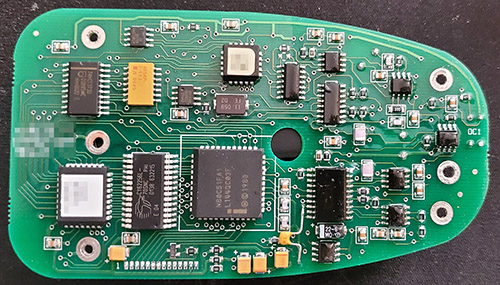
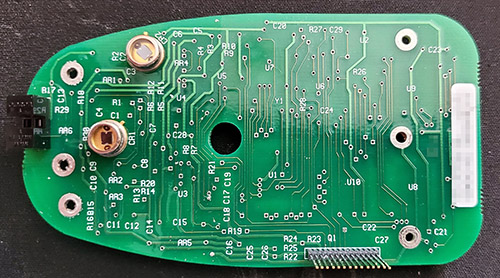
The Ware for April 2023 is shown below.
Another PCB with a funny shape, this time from a different era…but what does it do?
Thanks to artemb for contributing this ware!
Update
Still no correct answers, so here’s another hint. See that connector in the lower right hand corner of the bottom side of the board? Something stacks on it, and it looks like this:


This looks like an early optical mouse that requires a reflective X/Y grid mousepad?
An early version of an IR thermometer gun? The photointerrupter on the left would be for the trigger.
What’s most puzzling is the header, presumably for a display and power, is on the same side as the sensor(s). I would have expected that on the opposite side facing the user.
CR1 would be the IR sensor, CR2 the ambient light sensor.
That’s got 32K of SRAM on that 80C51 and the flash is probably at least that size. That’s a *ton* of memory for a mouse! There’s also way too many pins on that board to board interconnect for a mouse. Also, those optical detectors CR1 and CR2 only have two pins, you’d need quadrature detectors for a grid mouse. It does have what looks like a quadrature optical sensor for some kind of slot interruptor (like a mouse wheel).
Were there reflective XY grid mice late enough to have scroll wheels? I thought those two time periods were disjoint.
I almost feel like the mouse idea is a red herring and that bunny is trolling us.
The XTAL is good for UART speeds up to 230400 bps and all the common frequencies below that.
The chips date to just after 2000 to mid-late 2001. Whatever this is must need to speak pretty fast. Possibly they chose it because the 80C51 is very inefficient with clock cycles and they needed to do some actual calculations–which would explain the huge SRAM and FLASH.
CR1 and CR2 are mounted 45 degrees rotated from each other which seems to be by choice as there’s plenty of room on the PCB for them to be at pretty much any arbitrary rotation. Why? Are they polarized or something? And, if so, why 45 degrees? You’d expect 90 degrees or something.
I think you’re onto something – CR1 and CR2 (photodiodes?) are aligned (and rotated) with the prominent hole in the middle, although the opto-interrupter isn’t, which is curious. Also note the “OC1” designator on the other side from the opto-interrupter – could they be using it for serial comms??
Other observations – power appears to come in via the multi-pin connector, it has an DS1232 watchdog/reset chip, there are two programmable devices (flash for 8051 & 20-pin ?PLD?), only the top half of the board has conformal coating, 6 screw holes seems excessive (only 2 electrically connected and common, so not battery), and traceability appears to be important enough to have a barcode/serial number.
It looks like a keyfob. But everything looks like a keyfob when you don’t know anything about hardware. Hope you’re well, bunnie! <3
Hope you are well too, caustik! long time no say <3
Some kind of a colorimetr
Board shape is very similar to the Bayer Ascensia Entrust glucose meter shown on this page:
http://jaanus.tech-thing.org/teardowns-and-reviews/glucose-meters-teardown/
The optical sensor on the end could be to detect insertion of a test strip. And the header would interface to an LCD board that sat on top.
But would a glucose meter have a couple photodiodes facing in the same direction as where the top display PCB would be?
Might be. Maybe that’s why they only use conformal coating on one side, to help prevent blood from shorting out stuff. It is also in a shape that is very holdable.
My first guess was a fancy steam iron PCB.
Glucose meter was also my first guess. Sensor arrangement is a giveaway.
A glucose meter would justify the huge memory and the relatively simple/expensive processor setup. Because, in 2001, who bought name brand Intel 80C51 chips? Name brand top tier) SRAM? Someone put some cash in to this design and wasn’t working very hard to reduce costs–so it had to be for a relatively expensive device.
Regulatory compliance and guarenteed part availability would have been much more important factors for the manufacturer as well–hence the name brand parts.
It might also explain the confiormal coating on the upper part of the board–the area near where the test strips would be inserted would have the posibility of being exposed to fluids.
The overly rugged mechanical design would also be explained by it being a medical device that is often used by seniors. With their decreased grip strength and motor control, drops are much more likely, so surviving them would be more important.
I’m thinking it could be a hand-held barcode scanner, with the scanning being done by mechanical means.
Auto day/night adjusting rear view mirror for a car.
The new photo doesn’t help me at all. I hope it helps someone else, though. I’d hate to see one of these go unsolved.
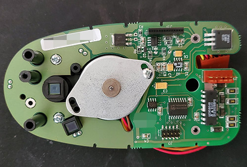
This board has some interesting optics which correspond to the sensors we saw on the other board–one assumes they’re some kind of light source and optics and/or filters of some sort.
In the center we have a stepper motor with some pretty simplistic control electronics, so we’re not doing any fancy motion control, more of a ‘move one direction, stop, move back, stop’ kind of mechanism. Enough to pull in a test strip of some kind I’d assume.
That’s about all I got for this 20+ year old device that was already on its F revision back then.
Looks like a primitive fingerprint enabled door lock to me.
Could this be an iDrive or similar device from the automotive realm? iDrive is the central multifunctional knob in the center console of BMWs, I think the feature was introduced back in 2002 or so and constantly developed. Other manufacturers jumped the train, too. Chips date from 2000 or 2001 mostly.
These specific closeups are not from a BMW controller apparently but look very familiar and the device might serve a very similar purpose.
The two optical sensors in the photos presented first match the position of what looks like 2 IR emitter diodes in the new picture, probably resembling a rotary encoder based on a photo interrupter disc? Like this one:
https://www.semanticscholar.org/paper/BMW-iDrive-automotive-hid-device-in-EFIS-control-Such%C3%BD-Paces/21509cb1848c42d90ef228844955eb80f749f919/figure/5
The central motor could be used to provide force feedback (that’s what BMW did for the first “1” series cars), and the interrupter at the bottom side of the board (?) might be used to detect whether the knob is pushed.
It would be a pretty complex circuitry for a rather simple task but overengineering is omnipresent in automotive so why not?
I can’t explain the partial conformal coating though…
Other guess: a 3D mouse for CAD?
3D mouse for CAD was also my first guess
I guess this optical sensor analyzes liquid (blood?) with PD/LED + photo interrupter, and the motor is for the tube pump. Silicone potting made me think this could be a medical device.
My guess is that it is part of a spectrometer or spectrophotometer. The two photodiodes measure reference and sample, and the stepper motor introduces filters and/or shutters into the beams. Or maybe a colorimeter which performs a similar measurement but to sense color of paint, etc. I think the conformal coating is because the low level photodiode conditioning circuitry is in that area and they need to avoid board leakage current.
I’m wondering if Bunny’s getting tricky, and there’s a *third* board or mechanical layer that goes between these two. Given the length of the inter-board connector pins and the black plastic standoffs/locator pins, there doesn’t seem to be much room for a sample-handling mechanism. The short standoffs right next to the stepper don’t mate with anything on the first board. Of the three longer standoffs, only the middle one appears to have screw witness marks, and the other two have large inner diameters that don’t look suitable for screws. So the two outer ones locate to something on a third board, the corresponding holes on the first board screw into the back side of whatever that is, and only the middle standoff has a screw to affix the whole sandwich? There’s also at least some standoffs missing from the other end of the boards, and the there’s something that goes in the middle hole on that end too.
The two sensors are different, but the LEDs look identical and presumably have the same spectrum. Maybe the sensors are high/low-res rather than different spectrum sensitivity. The first sensor is perpendicular to the center of the stepper shaft, but the one at 45 degrees isn’t. I’m guessing the stepper doesn’t rotate a disc with the sample on it. It could still be an injestion mechanism if the sample was a ribbon or liquid; maybe the stepper is for a peristalic pump.
Where’s the power come in? J2 on the second board?
The square sensor, especially, sure looks like a 2D imager.
This looks pretty thick and chunky for a hand-held device.
Wild guess–automated urine culture or blood sample analyzer, the kind that take pictures and count stuff.
I concur that there seems to be something missing. That stepper has to control something after all. And I agree that the tilt of the second LED has to mean something. It makes me wonder fi they have some kind of built in optics that are rotation dependenet.
If the shaft did rotate something around, the two LEDs are on different diameters, so that could justify the different rotations–they could both be oriented relative to the circular ‘sample’. Note that if they are, then they are now 90 degrees rotated from each other as one is parallel to the radius and the other is perpendicular.
What does J2 go to? (on the board with the stepper)
I think it’s a programming or debug header; there’s nothing to lock in the mating socket, so must be temporary. Only four pins appear connected. Pins 1 and 4 go to ground, and guessing the inner two are serial/JTAG etc.
Oh, wait. It’s two rows of pins. Still a temporary connection.
It could be held in place by the various screw holes in the board. Locking connectors are only needed for cables, not for board to board.
I think J2 is the I/O, limited as it may seem. The chip nearby, MC145406 is a 3 channel serial transceiver. Otherwise, the I/O must be on the other side of that board.
The opto interrupter near the photodiodes may simply be an interlock to prevent operation unless all the covers are in place. I have seen this in instruments which have HV and/or UV light sources. That fits with my spectrometer/spectrophotometer idea because those usually have a xenon or deuterium arc lamp as the light source. If so, that stuff, as well as the optical path through the sample would be behind the black plastic we see.
I like these wares that go on for awhile!
I’ve been keeping the spectrometer/spectrophotometer idea general, but specifically I think this is a HPLC detector. The build quality is in line with scientific lab instruments like that.
I’m out of idea so i’ll just go with an ABS
I just feel like there should be some kind of rotary encoder involved with this stuff. i said ABS, but it could just as well be part of some some kind of robotic arm … or not.
The two optics both have a trans-impedance-amplifier, also there seem to be some kind of optical filters (perhaps band-pass, polarization) in the optical assembly.
The stepper motor most likely moves the samples from one sensor to the other.
I don’t see the light-source or any other kind of excitation for the sample. Perhaps the 2-pin THT parts next to each optical assembly are the pins of LEDs.
Thus Spectrophotometer for biological samples seems plausible.
Those device typically measure with 600nm and a UV source (they are named UV/VIS spectrophptometer). This is consistent with the two positions. The conformal-coating also matches that use-case. It is quite common to spill some liquid in those devices when handling the sample cuvette.
So my guess is biological lab equipment to measure OD600 of microbiological cultures.
The two positions of the sensors are spaced with a 45° angle on a circle with the center on the motor. That means there are 8 total positions on the wheel.
https://i.imgur.com/VLzjIc8.png
I assume the device looks somewhat similar to this one:
https://www.scinteck.com/uploads/1/9/7/6/19761741/s535115837287589659_p263_i15_w480.jpeg
I am intrigued by the power transistor Q1 and thinking about what its function might be. It is MJD 44H11, which is an 8 Amp 80V NPN. That’s a lot of rating for something on these little boards. And it is on a substantial thermal pour. So I think it is being run linear, and that may fit with the idea of the 3 pairs of pads being LEDs on the other side of the board. Maybe one photodiode measures the raw light level and keeps it constant by controlling LED current with Q1. Keep in mind that LEDs in 2001 were not what we are used to today! But they did have blue ones and white ones based on those. And some long wave UV ones. I’m not sure whether the 235 nm light often used in UV spec instruments could be generated by LEDs in 2001.