The Ware for October 2024 is shown below.

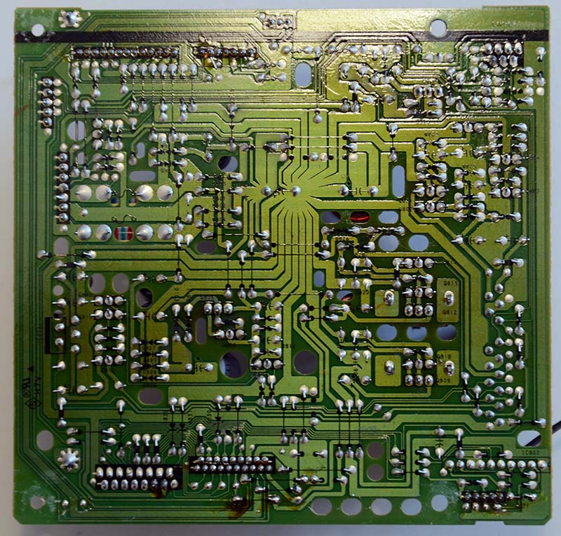
This one should be a smidge easier to guess than last month’s ware. The main reason I liked this ware is actually the board shown below with the prominent star-routing. It’s such traditional hand-routing work, I love craftsmanship like this.

For completeness, this is the top side of the board shown above:

Thanks to spida for sharing this ware!
Also, just in time for Halloween, this spooky ware made its way to my desk:

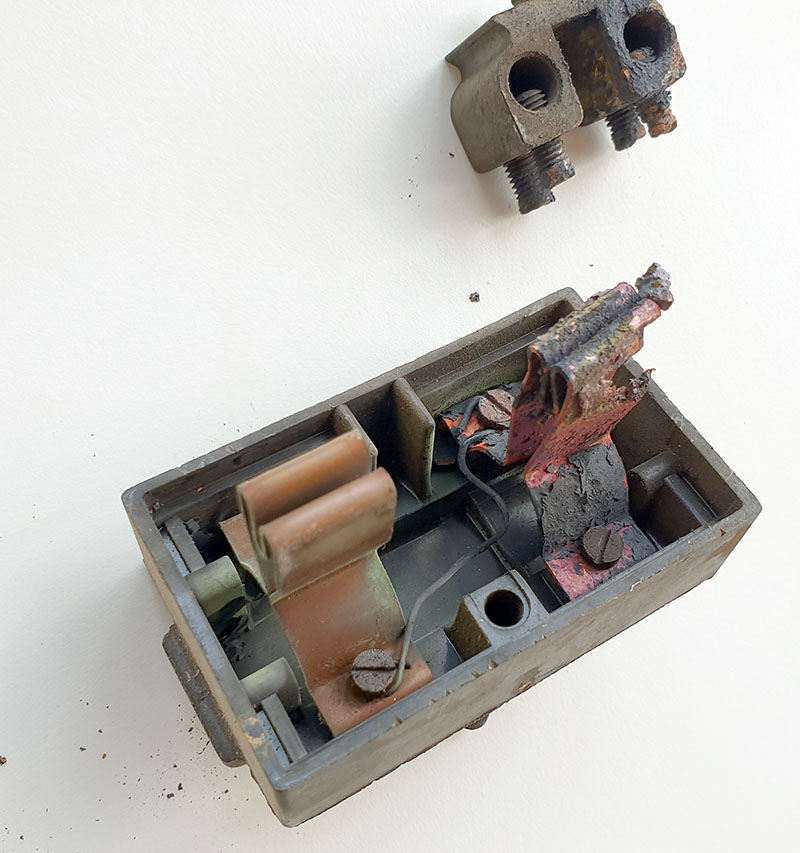
This is the “fuse box” that was connecting my flat to the power mains. I live in one of the oldest buildings in Singapore; I’m pretty sure this is part of the original wiring, which makes it over 50 years old. I guess at some point, someone decided to replace the fuse with a…wire.
OK, sure.
That’s spooky enough as it is … but also not so spooky, given that downstream of it are two very modern circuit breaker boxes with GFIs. So, I think its sole purpose was to give the power company a “switch” to disconnect the power meter from the mains, if they had to service the meter.
However, the fuse cartridge probably also played some role in pushing the copper fingers into the receptacle, so without the fuse in place, the fingers were not pushing firmly against the terminal block. Over time, one of the fingers turned into a miniature electron milling experiment.
The air quality sensor in my place had ticked up slightly a couple days ago, and I thought maybe it was the haze coming back; but then last night I smelled an acrid smell I know all too well, and when I poked my head out I heard the slight crackling of electricity arcing coming from the mains panel, and knew I had to drop everything and look for the source of trouble.
So, the servers were down for a bit yesterday, but at least I have power now and only a slightly charred mounting board at the power entry point of the unit, instead no electricity and an entirely charred unit. My place is now slightly less cursed, but if I were to be honest, this is probably not the most cursed circuit on the premises…my lab is a veritable crypt of cursed circuitry!
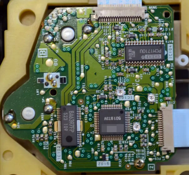
The style of PCBs immediately made my think of 90s VCRs and TVs (I think I can almost smell the gentle aromas from here).
A couple of the part numbers give hints:
PCM1710U = stereo audio DAC
BA6397FP = CD player motor driver
Probably pre-DVD because I suspect a seperate DAC on its own little PCB wouldn’t be done when you have a video codec chipset that could integrate those features. Perhaps.
With this PCB style it’s specifically a TV/hifi appliance-scale device, not something that needs to be compact or portable.
Guess: Consumer CD player, or maybe a more exotic audio disk media like Minidisc or perhaps Laserdisc?
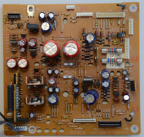
I’ll add that it’s a subtly interesting power supply.
Two stripy fuses on the right and a few bridge rectifiers. That means there is a big wound transformer in the box with this unit, with at least two sets of outputs.
There are no inductors on this PCB, so all of the transistors on the PCB must be acting as linear regulators. That means the power budget for this unit is small, probably 10W or so.
These design choices seem to confirm my elimination of a DVD player or VCR machine, those tended to have little self-oscillating power supplies like one of these:
https://ludens.cl/Electron/dcdc/dcdc.html
Rather cute things, but I don’t think they used the magnetics very efficiently, so they only made sense in an era where transformers were cheap but good switchmode control electronics were expensive. That pushes my date estimate back to late 80’s early 90’s.
The two white components in the middle of the PCB are mysteries to me. “J only” = “japan only”? I think they’re fuses, perhaps Japan is more flammable… wait a second, your story about your apartment’s power isn’t completely unrelated to you opening this device up, is it? Fess up :)
On the lower-left of the power supply board is a little display PCB. This suggests the whole thing fit into a low-profile case. A dedicated CD player is starting to seem more likely now — low power, mains transformer powered, linear regulators, low density single-sided phenolic PCB style, chip numbers that make sense.
(That probably means I’m miles off like usual :D)
(Link in my other comment goes to the completely wrong type of power supply, sorry. I’m thinking of a mains->12V small flyback PSU, not a 12V->mains inverter. Woops. The rest of my comment regarding cost of magnetics vs switchmode controllers for this style of design still holds, however).
This has SONY written all over it, especially the style of routing and the arrow shapes pointing towards mounting screws. My guess would be a CD or MD player’s servo and controller board. One of the motors is the spindle motor whereas the other one is for moving the tray in and out. The solder side of an end-of-travel contact can also be seen. The flat flex ribbon pointing away from the spindle motor is probably going towards the laser pickup, and the other flat flex connects the assembly to the controller board (white connector in the bottom middle section)
I’m building a backyard solar array, my first hobby project requiring an electrical inspector. Electricians in my city cost way too much, plus I previously installed a heat pump DIY, including my own wiring, and I don’t want the inspector to see what I did.
So I’ve been grumbling about this situation, at the same time grateful that the U.S. National Electrical Code does at least keep amateurs from burning their houses down.
Inspired by your fuse box, how about a crowdsourced send-in-your-photos campaign: absolutely terrible or vintage electrical work. There should be plenty of examples from around the world, some scary, some beautiful. In certain locales, it is popular to steal electricity from neighbors or bypass meters. In others, electricity isn’t 24/7, and there are creative ways to address that. My favorite is multiple DIY hydro power generators floating in a Serbian river. Before my friend’s grandfather retired from a Turkish power company, he collected some fabulous high-craftsmanship equipment pulled from service in power plants and substations. You get the idea.
You can find many such examples on the reddit sub forum for electricians.
Definitely CDs. The PCM1710U takes in serial data as 16 bits for the left channel, then 16 bits for the right, same as a CD. The BA6397FP is a 4-channel BTL driver for CD drive motor.
The PCM1710U also looks like it has a 1995 (21st week) date code?
That’s not a wire replacing a fuse, that is, or at least should be, “fuse wire”. The whole assembly is a “rewireable fuse”. There’s a ceramic channel that ran between the terminals to hold the fuse wire missing from that fuse. One bought “fuse wire” which was wired between the two terminals. Fuse wire came wrapped on small sheets of cardboard that typically held several different ratings; for domestic use in the UK the cards usually carried 5A, 15A and 30A.
It’s certainly acting as fuse wire! But there ISN’T a ceramic channel, and there ARE sockets for a cartridge fuse…
I think Ian is correct for this example – the rounded parts of metal are to hold the (missing) ceramic channel. I suspect someone disassembled it a little too far when last replacing the wire and said “there I fixed it!”
Search for “wylex rewirable fuse holder” for slightly better made examples.
Yeah, this has Sony CD player written all over it.
Searching for “ba6397fp board” brings up the exact same board: https://spares2repair.co.uk/sony-board-bd-board
Part number: A4673402A (but there are others: A4649610A
The same board is used in 150+ Sony products though, so that doesn’t narrow it down much. I could probably go down through the product list and dig out all the service manuals and find it. However, just from trying a few, it looks like multiple Sony products also share the same power board… so I wouldn’t be surprised if the NTW photos alone cannot uniquely identify a product.
The PSU is a dedicated board with lots of connectors, which suggests a larger system (all-in-one home audio system), not a self-contained CD player. There is also a hint: the “J only” labels suggest this is a Sony device with a “J” product variant. Unfortunately, the two I found in my parts list (CHC-P11J, HCD-H11) are just aliases and use a different power board, which is different from this one (but looks kind of similar style). Newer products tend to integrate the main board and power/amp board. But my product code list is probably incomplete…
Taking those as a lead, I started looking for similar Sony systems of that vintage, and I landed on the HCD-D1/T1… which happens to be a perfect match for both boards, despite not being in my original equipment list for the BD board. :)
https://www.manualslib.com/manual/3318397/Sony-Hcd-D1.html#product-HCD-D1
Soo, Sony HCD-D1 or HCD-T1, which are parts of the CMT-D1/CMT-T1/CMT-M1 component systems.
CD player! I wish there were a way to embargo comments for a few days; I’m always too late to put in a guess before there’s already a lot of great scholarship. And the one time I nailed the ware before everyone my comment wouldn’t post for some reason! Happy Halloween y’all.
The ware is most likely a Sony HCD D11/T11
Looking at the PCB, it looks like a Sony board from the 1980-1990s due to the greenish yellow tint and the very detailed marking on the PCB.
1) the cd control IC, plastic surround around the first board and the multiple motors present suggests that it will be operating a cd tray so not portable discman (googling sony hifi disc board proves it)
2) the power needed for the board in the second/third picture will be not feasible for a car stereo, and the grounding screw hole at the top left proves it, the holes on the board is interesting as it looks like an attempt to passively cool the board
But its not enough, we need the model name
so.. as we got the board part number from the search, now we look at all the systems that have it (which is admittedly a lot)
Looking at tons of service manual, We finally found the system that it (most probably) came from, A Sony HCD D11/T11 HiFi Tuner, Cd and Preamp, intended to be used in a mini HiFi System
Hi all, Does anyone know of free software that’s reliable for keeping track of clients and scheduling appointments, preferably cloud-based.
It looks like a Sony motherboard.
Merci pour cet article !