Archive for the ‘chumby’ Category

Chumby’s Launched!

Monday, February 25th, 2008

Well, time for the shameless plug. You’ve probably seen the posts on how the hardware is manufactured. Finally, after much hard work by the whole team, the Chumby is officially launched! If you’ve been waiting to get one, now’s as good a time as any other to buy one. As part of launch, the chumby website got a face-lift, and the launch firmware includes a lot of nice new features, bug fixes, and usability enhancements.

CNET and Gizmodo already have reviews of the chumby up. Chumby also has a set of launch partners, including CBS, Food Network, MySpace, MTV Mobile, Shoutcast and the Weather Channel. These launch partners, along with a growing community of independent widget developers, have contributed to the hundreds of widgets available now for the Chumby.

24C3

Monday, January 7th, 2008

I had the fortune this year of being able to attend 24C3, the 24th annual Chaos Computer Congress. The conference was a lot of fun–probably the first time in a long time (at least since chumby started) that I got to sit down and just hack for a couple of days on fun projects…in between going to really interesting and stimulating talks, and enjoying Berlin’s nightclub scene. C-base was quite fun (DJ Vela played a great set), and there’s no closing time in Berlin: one club we visited had a line-up that went to 10 AM (I gave out around 6 AM…).

I had the privilege of sitting at a table in the Hackcenter with a group of console hackers that were scary smart and doing very cool things that shall remain unnamed, at least until they are ready to disclose their fascinating findings. It’s quite humbling and inspiring to watch them work. I also got a chance to chat with some silicon hackers that presented a great talk about reversing CRYPTO-1. It’s always a pleasure to be exposed to so many brilliant minds and osmotically absorb knowledge and techniques by just being around them–but that’s one of the reasons you go to a conference, after all.

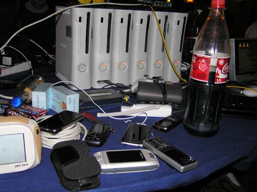
The table I was sitting at had a half dozen Xbox360’s brought in by tmbinc and ole, set up as a Linux cluster. People had a lot of fun hacking the boxes.

While a lot of American hackers drink Red Bull, it seems the drink of choice by German hackers is “Clubmate”, pronounced “cloob mah-tay”. It’s an herbal energy drink that’s a bit of an acquired taste, but it definitely “works”.

I decided to play with phidgets while I was at 24c3; a few months ago a chumby user mentioned it in the forum and I bought an 8/8/8 interface board (8 analog, 8 digital in, 8 digital out) and a few of the 3052 solid state relay boards (there’s also a 3051 relay board for those who want to control lights and appliances). Of course, “spare time” never happened, but the Hackcenter in 24c3 was the perfect place to steal away for a couple days and play with one of my favorite pastimes, namely robotics.

Cross-compiling the basic Linux phidgets driver was fairly straightforward; I just had to modify the makefile to explicitly use arm-linux-gcc instead of the default host compiler. I then copied the libphidget21.so onto the chumby root file system–not quite as easy, as it’s a cramfs read only filesystem. Since I didn’t have my full chumby development environment on hand, I grabbed one of the chumby OTA update distribution filesystems, mounted it as a loopback volume, tar copied the contents out, added the library files, and then regenerated the cramfs filesystem. It’s a lot of work if you’re not comfortable with Linux; an easier way to handle this is to just statically link your binaries against libphidget21.a.

Compiling the phidget example file was a bit more difficult. The standard header set for the phidget examples were missing some files that I needed, which took me a while to figure out. Instead of onion-peeling to try and figure out exactly which header files were missing, I just pasted in a whole pile of them and finally it worked.

The other key thing you need to do on the chumby is to mount the usbfs filesystem–this would have taken me forever to figure out if tmbinc hadn’t chimed in–using the command “mount -t usbfs null /proc/bus/usb/” did the trick.

After doing all this, I was able to run the ifkit.c example file (contained inside the phidgets driver tree) and observe the 8/8/8 sensor board returning interesting results.

The next step was to get the phidget to actually do something. So, I went across the street to the MediaMarkt shopping mall and bought a random RC toy car while grabbing a bite to eat. Ole and I pondered for a while about the best way to connect the phidget to the RC car. The steering mechanism for the car didn’t use a servo motor as I had suspected, it actually used an underdriven DC motor that relies on its stall current to force the wheels left or right. My guess is that the motor controller board in the car did a PWM or had a current limit built into it to prevent the motor from burning out. Driving this full tilt with a simple solid state relay was almost sure to cause trouble, so we decided to take the remote controller circuit board out of its case and wire the solid state relays across the slide-switch terminals that the RC controller used to control front/back and left/right directions. So the control path was like this: chumby application -> phidget driver -> USB -> phidget board -> solid state relay -> RC controller switches -> modulated to 27 MHz -> transmitted over a distance of 1″ -> demodulated -> motor driver -> motors. It’s a bit like IM’ing someone in the same room with you, but hey, people do it sometimes. We mounted the phidget controller board and the RC controller inside the housing of the RC car, so you couldn’t see the hack–all you saw was a USB cable coming out of the car body, and then this was plugged into the chumby, which was taped to the car’s hood.

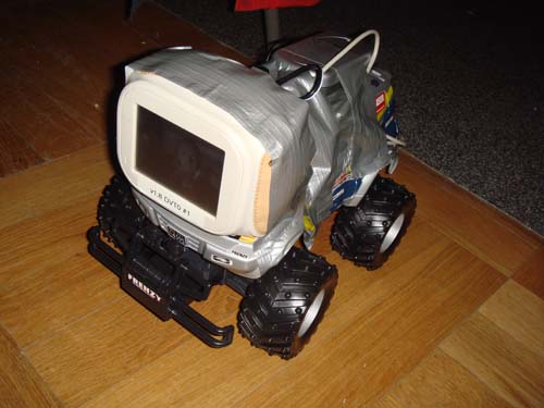
That’s what the initial assembly looked like at this point; we used an Energizer ER-PHOTO battery pack (mentioned in the previous blog post) to power the extra electronics. Plenty of duct tape was used, which is charmingly referred to by Germans who don’t know the English term for it as “that silvery tape that MacGyver uses”.

Of course, driving around an RC car via a chumby with a serial debug cable connected to it is really lame. Fortunately, I had a second chumby (actually, it was tmbinc’s chumby), so I wrote a quick server/client protocol that establishes a UDP connection between the two chumbys over the WiFi link that allowed me to stream basic commands to the car (basic meaning, a single 32-bit unsigned int containing a bit vector of commands). Ole then suggested that it would be really cool to use the accelerometer in the chumby to control the driving of the RC car by tilting the chumby, so I hacked up the server to transmit the pitch and roll of the chumby in degrees to the client. I also used the the bend switch as a “zeroing” function, so that if you squeeze the chumby, the car immediately stops and the relative “zero tilt” position is recalibrated.

[flashvideo filename=images/remote_control1.flv /]

Above is a video (with sound) of the wifi chumby-car driving around. The room at the Hackcenter is of course kept very dark, so all you can really see is the chumby’s LCD screen going by, and you can see me tilting the other chumby around to control the direction of the car–and you can hear the motors of the RC car doing their thing. Here’s a link to the source code used by the system.

Of course, this wasn’t good enough. You could only drive the car around within visual range, but WiFi can go much further than that. If we could only find a way to see what the car was seeing…

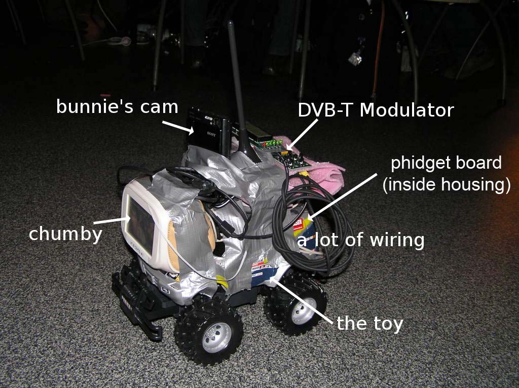
It just so happened that tmbinc and ole brought along a complete DVB-T encoder/transmitter/receiver setup–for what reason, I’m not sure, but hey, that’s the joy of being around hardware hackers, they just have the coolest stuff on hand (Ole had a rad ERSA gas-powered soldering iron, for example). So, we soldered on a power tap to the chumby (fortunately, the DVB-T encoder could also eat the 12V supplied by the ER-PHOTO pack), and taped the DVB-T encoder onto the roof of the RC car, after wrapping it up in some protective foam. We also taped my Sony Cybershot DSC T-10 camera onto the car, which fortunately had a PAL video output that we could feed right into the assembly. We then borrowed a pair of DVB-T antennae from another hacker who “just happened” to have some of these on hand. Finally, we strapped on this super-bright battery powered flashlight that Ole had, and we were ready to rock.

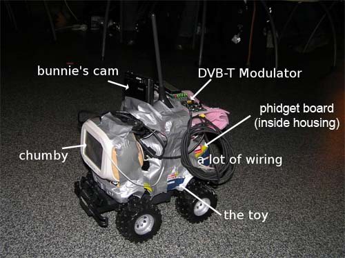
The above picture was ripped from tmbinc’s blog. Click on the photo for a larger version.

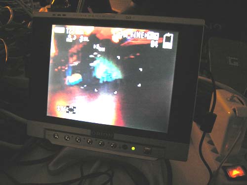
Above is the car’s eye view of the world. The video was being compressed on the fly into MPEG-2 and transmitted over the air, so it was a bit laggy–about a one second delay, so driving the car took some skill to anticipate where you needed to turn before it happened.

As a final touch, we configured the chumby on the RC car to play Shoutcast streaming radio (hey, it’s still a full-featured chumby, showing widgets and playing music like it was designed to), so that as the car drove around it played some bright techno music to announce its presence.

[flashvideo filename=images/remote_techno.flv /]

Above is a video taken from the car’s-eye view, with the toe-tapping techno sound track streaming over Shoutcast to the chumby and being decoded while the chumby also handled the car driving task.

The final control paths for the system thus looked like this:

sensors -> chumby server app -> UDP packet -> 802.11 wifi transmitted over 10’s of meters -> client client app -> phidget driver -> USB -> phidget board -> solid state relay -> RC controller switches -> modulated to 27 MHz -> transmitted over a distance of 1″ -> demodulated -> motor driver -> motors

Sony DSC-T10 camera -> PAL -> DVB-T encoder -> MPEG-2 format -> DVB-T wireless transmission over 10’s of meters -> DVB-T receiver

Plus, of course, the normal widget stream coming from the chumby servers in the US via the Wifi interface as well. After all, what Wifi controlled toy car isn’t complete without streaming internet radio, Flash movies of Chuck Norris facts and “interesting” Flickr streams playing on it.

It’s a bit of a Rube Goldberg machine, but that’s the joy of abstraction (and abusing abstractions).

And that’s what I did over my Christmas holiday :-)

Popsci Chumby Hack

Wednesday, November 28th, 2007

Popular Science’s blog just ran a piece on reskinning a chumby. Now that chumbys are available for general purchase by those willing to participate as a “Chumby Insider” and are running around in the wild, it’s nice to see that people are opening them up and doing something new with them!

I have to admit, it’s a little bit weird being on the “other side” and seeing your stuff in a tear-down, but it’s very rewarding to see it all the same. I look at the circuit boards and the plastics assembly and run through the manufacturing operating procedure in my head, to see if there are any flaws, obsessing over product quality…instead of seeing the opportunities of what you could do with the naked hardware. Maybe when you stare at something too hard you become myopic. I’ll keep an eye on the hack posts around the web to help my mind stay open to new ideas.

Incidentally, you don’t have to solder wires directly onto the power switch. The same signal is routed to a much easier pair of terminals (pins 9 and 11) on the chumbilical connector! I picked a classic 26-pin 0.1″ square-pin dual row connector for maximal hacker-friendliness.

Made in China: Chumby

Friday, November 23rd, 2007

After many months of hard work, chumbys are finally rolling off the line from China in volume. I just got back from an operations review of the factories in China. You can see the final assembly process for the chumby in the movie below!

You can (finally) buy a chumby now simply by visiting the Chumby on-line store (no more waiting for invitations), so you too can have a chumby Christmas (while supplies last). The firmware is currently at the “Insider’s” revision, which basically means that you can expect an over the air (OTA) update via WiFi to the full launch version, for free of course, once the launch version of the firmware is available. The key difference between the Insider’s version and the launch version is that you can get the Insider’s version today, and the launch version will have new software features, such as more Internet music sources, that have been popular requests by many of chumby’s early adopters. The neat thing is that once the OTA update issues simultaneously with the product launch, Insider’s versions will be upgraded to be feature-identical to the launch versions. In general, one of the strengths of being open with customers is that chumby gets rapid, helpful feedback that allows them to target efforts to continuously improve the software on the device via the automatic update feature.

This is me at the logistics depot in front of a couple of pallets of chumby devices bound for customers…

Since the chumby hardware is sold at near cost, we decided it didn’t make sense to offer a “guts only” hacker developer kit, at least not yet, because it’d sell for only a little bit less than a normal chumby. However, I’m working on getting an offering available for a plastic parts only kit for the people who want to case mod their chumbys.

ESD and Me

Sunday, November 4th, 2007

Well, Chumby is finally shipping units in volume. You can’t go to the website yet and just buy one because we’re working through the long, long list of emails we received from people who asked to be notified when chumby devices are available for sale — there’s quite a backlog of orders there alone, although a few have shown up on ebay! I’m working on making some embedded developer (bare board) and craft (outerware only) units available for sale someday, separate from the consumer units. Hopefully that will make the core hardware more available to interested hackers and crafters.

The natural consequence of having many units out there is that we’re starting to see some interesting customer return cases. I recently got one unit that was destroyed due to an ESD (electrostatic discharge) event coming in from the power cord: the AMS1117 regulator that supplies the standby current for the CP and system management controller had been zapped. Interestingly, the unit worked for about an hour before it ceased operation.

This failure is particularly intriguing because there is a series of ESD protection devices between the AMS1117 and the power cord; at the front line, there is an AVX TransGuard transient voltage suppressor, then a set of EMI filters, diodes, fuses and so forth. Presumably, either some monster ESD event happened that not even these barriers could absorb, or the device was damaged on the factory floor prior to assembly. To investigate, I had the device decap’d and imaged by FlyLogic, and I found the results interesting enough to share.

Here is an overview of the damaged chip (click on the image for a much larger version).

The spot with ESD damage is in the lower right hand corner, zoomed in here.

The path that the discharge event took between the output pin and the pass transistor of the regulator looks a little bit like a river channel that bends slightly up and over to the right. You can see how the metal was splattered and migrated by the ballistic motion of the electrons flowing by. This migration of metal eventually caused the pass transistor to get shorted out, so, unfortunately all the 3.3V devices downstream of this regulator got stuck with about 12V across them. Toasty! Fortunately, the PTC fuses on the board and other current-limiting mechanisms kicked in so the board never got dangerously hot.

One thing that struck me about this particular layout is the apparent lack of any on-chip ESD protection devices. Even though this is a big bad analog process, it seems non-intuitive to me that a bare device can stand up to the 2kV human body model tests that’s pretty much considered the minimum bar for ESD protection. Even if the device alone could stand up to the failure, it seems that what went wrong here was current arcing between two adjacent pieces of metal, possibly aggravated by the corona effect at the corners of the metal layout. At any rate, a device with no local ESD protection can be very susceptible, so perhaps even despite the precautions taken in the board layout, an external ESD event could blow up this chip.

I could be wrong, but perhaps I should now be looking for a chip vendor that was a little more fastidious about their ESD protection to prevent more unhappy customer return events. If any readers have some experience with analog chip processes like this, I’d appreciate a comment about the level of ESD protection you had to incorporate in your chip designs!

The ESD damage wasn’t the only interesting thing about the chip however. I also noticed burned out metal elsewhere on the chip:

There are several burned out spots like this on the left hand side of the chip.

This was a neat find, because this shows you how they trim these voltage regulators in the factory. For those not familiar with analog chip design, the accuracy of an integrated polysilicon resistor in an analog-optimized process is about +/- 20%. On a generic digital process, the accuracy is typically much worse (on the other hand, matching between devices on the same chip can be extremely tight and the quality of the match is proportional to the area of the device). Thus, when a chip advertises +/-1% accuracy for voltage, it has to have some kind of post-fabrication trimming mechanism built in.

Basically, the trim mechanism is constructed using a ladder of resistors in series, with shorting metal straps in parallel with each resistor. Therefore, when the chip is first manufactured, the calibration resistor ladder has a nominal resistance of nearly zero ohms. At wafer test, the chip’s output voltage is measured, and resistance is selectively added to this calibration ladder by using a series of high current is pulses to selectively blow the metal straps. Thus, the native chip design, without calibration, always shoots too far one way on the voltage, so you can always correct the problem by only adding resistance to a calibration ladder. If they did the design right, they would have it start with the voltage too low, so that if a fuse was only partially blown and it managed to repair itself (this does happen), you would only end up passing too little voltage to the regulated load, instead of too much — under the theory that if you are to have a malfunction, it’s typically safer to push less voltage than too much.

You can see all the extra bond pads used for this calibration process along the left hand side of the chip. There are very deep “scrub” marks, so large, heavily weighted needles were used to touch down on the wafer. This was probably necessary because of the high currents required to blow the metal fuses. Other trim mechanisms I’ve heard of include poly fuses, eFuses, or laser trimming, but I had never seen one “in real life” — they had always been an intellectual curiosity that I’ve read about in a process manual or a journal paper.

Wow, this post turned out long…