Archive for the ‘Ponderings’ Category

WIRED Documentary on Shenzhen

Wednesday, June 8th, 2016

WIRED is now running a multi-part video documentary on Shenzhen:

This shoot was a lot of fun, and it was a great pleasure working with Posy and Jim. I think their talent as producer and director really show through. They also did a great job editing my off-the-cuff narratives. The spot in the video where I’m pointing out Samsung parts isn’t matched to the b-roll of Apple parts, but in their defense I was moving so fast through the market that Jim couldn’t capture all the things I was pointing at.

I haven’t seen the whole documentary myself (I was just called in to give some tours of the market and answer a few questions in my hotel room), so I’m curious and excited to see where this is going! Especially because of the text chosen for printing during my Moore’s Law explanation at 3:13 — “ALL PROPRIETARY AND NO OPEN SOURCE MAKES INNOVATION A SLOW PROCESS.”

:)

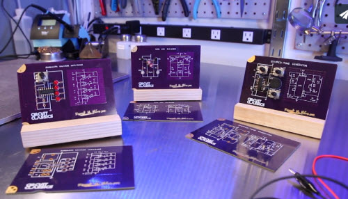
Circuit Classics — Sneak Peek!

Sunday, May 1st, 2016

My first book on electronics was Getting Started with Electronics; to this day, I still imagine electrons as oval-shaped particles with happy faces because of its illustrations. So naturally, I was thrilled to find that the book’s author, Forrest Mims III, and my good friend Star Simpson joined forces to sell kit versions of classic circuits straight off the pages of Getting Started with Electronics. This re-interpretation of a classic as an interactive kit is perfect for today’s STEM curriculum, and I hope it will inspire another generation of engineers and hackers.

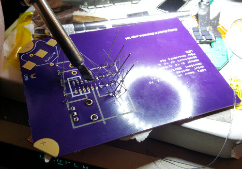
I’m very lucky that Star sent me a couple early prototypes to play with. Today was a rainy Saturday afternoon, so I loaded a few tracks from Information Society’s Greatest Hits album (I am most definitely a child of the 80’s) and fired up my soldering iron for a walk down memory lane. I remembered how my dad taught me to bend the leads of resistors with pliers, to get that nice square look. I remembered how I learned to use masking tape and bent leads to hold parts in place, so I could flip the board over for soldering. I remembered doodling circuits on scraps of paper after school while watching Scooby-Doo cartoons on a massive CRT TV that took several minutes to warm up. Things were so much simpler back then …

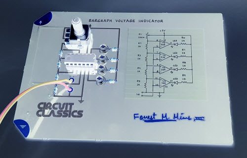
I couldn’t help but embellish a little bit. I added a socket for the chip on my Bargraph Voltage Indicator (when I see chips in sockets, I hear a little voice in my head whispering “hack me!” “fix me!” “reuse me!”), and swapped out the red LEDs for some high-efficiency white LEDs I happened to have on the shelf.

I appreciated Star’s use of elongated pads on the DIP components, a feature not necessary for automated assembly but of great assistance to hand soldering.

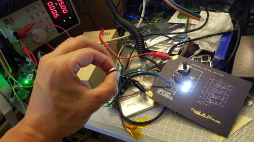
It works! Here I am testing the bargraph voltage indicator with a 3V coin cell on my (very messy) keyboard desk.

Voilà! My rendition of a circuit classic. I think the photo looks kind of neat in inverse color.

I really appreciate seeing a schematic printed on a circuit board next to its circuit. It reminds me that before Open Hardware, hardware was open. Schematics like these taught me that circuits were knowable; unlike the mysteries of quantum physics and molecular biology, virtually every circuit is a product of human imagination. That another engineer designed it, means any other engineer could understand it, given sufficient documentation. As a youth, I didn’t understand what these symbols and squiggles meant; but just knowing that a map existed set me on a path toward greater comprehension.

Whether a walk down nostalgia lane or just getting started in electronics, Circuit Classics are a perfect activity for both young and old. If you want to learn more, check out Star Simpson’s crowdfunding campaign on Crowd Supply!

Formlabs Form 2 Teardown

Wednesday, March 23rd, 2016

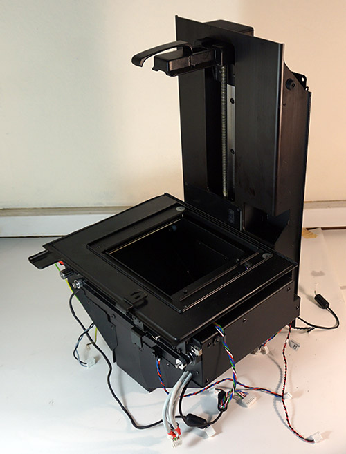
I don’t do many teardowns on this blog, as several other websites already do an excellent job of that, but when I was given the chance to take apart a Formlabs Form 2, I was more than happy to oblige. About three yeargalvos ago, I had posted a teardown of a Form 1, which I received as a Kickstarter backer reward. Today, I’m looking at a Form 2 engineering prototype. Now that the Form 2 is in full production, the prototypes are basically spare parts, so I’m going to unleash my inner child and tear this thing apart with no concern about putting it back together again.

For regular readers of this blog, this teardown takes the place of March 2016’s Name that Ware — this time, I’m the one playing Name that Ware and y’all get to follow along as I adventure through the printer. Next month I’ll resume regular Name that Ware content.

First Impressions

I gave the Form 2 a whirl before tearing it into an irreparable pile of spare parts. In short, I’m impressed; the Form 2 is a major upgrade from the Form 1. It’s an interesting contrast to Makerbot. The guts of the Makerbot Replicator 2 are basically the same architecture as previous models, inheriting all the limitations of its previous incarnation.

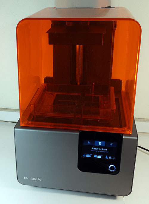
The Form 2 is a quantum leap forward. The product smells of experienced, seasoned engineers; a throwback to the golden days of Massachusetts Route 128 when DEC, Sun, Polaroid and Wang Laboratories cranked out quality American-designed gear. Formlabs wasn’t afraid to completely rethink, re-architect, and re-engineer the system to build a better product, making bold improvements to core technology. As a result, the most significant commonality between the Form 1 and the Form 2 is the iconic industrial design: an orange acrylic box sitting atop an aluminum base with rounded corners and a fancy edge-lit power button.

Before we slip off the cover, here’s a brief summary of the upgrades that I picked up on while doing the teardown:

  • The CPU is upgraded from a single 72MHz ST Micro STM32F103 Cortex-M3 to a 600 MHz TI Sitara AM3354 Cortex A8, with two co-processors: a STM32F030 as a signal interface processor, and a STM32F373 as a real-time DSP on the galvo driver board.
  • This massive upgrade in CPU power leapfrogs the UI from a single push button plus monochrome OLED on the Form 1, to a full-color 4.3” capacitive touch screen on the Form 2.
  • The upgraded CPU also enables the printer to have built-in wifi & ethernet, in addition to USB. Formlabs thoughtfully combines this new TCP/IP capability with a Bonjour client. Now, computers can automatically discover and enumerate Form 2’s on the local network, making setup a snap.
  • The UI also makes better use of the 4 GB of on-board FLASH by adding the ability to “replay” jobs that were previously uploaded, making the printer more suitable for low volume production.
  • The galvanometers are full custom, soup-to-nuts. We’ll dig into this more later, but presumably this means better accuracy, better print jobs, and a proprietary advantage that makes it much harder for cloners to copy the Form 2.
  • The optics pathway is fully shrouded, eliminating dust buildup problems. A beautiful and much easier to clean AR-coated glass surface protects the internal optics; internal shrouds also limit the opportunity for dust to settle on critical surfaces.
  • The resin tray now features a heater with closed-loop control, for more consistent printing performance in cold New England garages in the dead of winter.
  • The resin tray is now auto-filling from an easy to install cartridge, enabling print jobs that require more resin than could fit in a single tank while making resin top-ups convenient and spill-free.
  • The peel motion is now principally lateral, instead of vertical.
  • The resin tank now features a stirrer. On the Form 1, light scattering would create thickened pools of partially cured resin near the active print region. Presumably the stirrer helps homogenize the resin; I also remember someone once mentioning the importance of oxygen to the surface chemistry of the resin tank.
  • There are novel internal photosensor elements that hint at some sort of calibration/skew correction mechanism
  • There’s a tilt sensor and manual mechanical leveling mechanism. A level tank prevents the resin from pooling to one side.
  • There are sensors that can detect the presence of the resin tank and the level of the resin. With all these new sensors, the only way a user can bork a print is to forget to install the build platform
  • Speaking of tank detection, the printer now remembers what color resin was used on a given tank, so you don’t accidentally spoil a clear resin tank with black resin
  • The power supply is now fully embedded; goodbye PSU failures and weird ground loop issues. It’s a subtle detail, but it’s the sort of “grown-up” thing that younger companies avoid doing because it complicates safety certification and requires compliance to elevated internal wiring and plastic flame retardance standards.
  • I’m also guessing there are a number of upgrades that are less obvious from a visual inspection, such as improvements to the laser itself, or optimizations to the printing algorithm.

    These improvements indicate a significant manpower investment on the part of Formlabs, and an incredible value add to the core product, as many of the items I note above would take several man-months to bring to production-ready status.

    Test Print

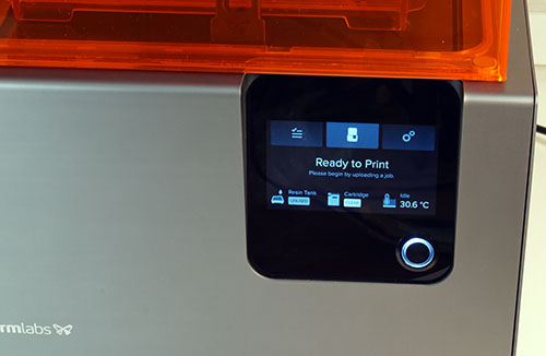
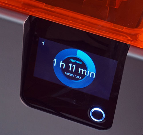
    As hinted from the upgrade list, the UI has been massively improved. The touchscreen-based UI features tech-noir themed iconography and animations that would find itself at home in a movie set. This refreshing attention to detail sets the Form 2’s UI apart from the utilitarian “designed-by-programmers-for-geeks” UI typical of most digital fabrication tools.


    A UI that would seem at home on a Hollywood set. Life imitating art imitating life.

    Unfortunately, the test print didn’t go smoothly. Apparently the engineering prototype had a small design problem which caused the resin tray’s identification contacts to intermittently short against the metal case during a peel operation. This would cause the bus shared between the ID chips on the resin tank and the filler cartridge to fail. As a result, the printer paused twice on account of a bogus “missing resin cartridge” error. Thankfully, the problem would eventually fix itself, and the print would automatically resume.


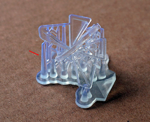
    Test print from the Form 2. The red arrow indicates the location of a hairline artifact from the print pausing for a half hour due to issues with resin cartridge presence detection.

    The test print came out quite nicely, despite the long pauses in printing. There’s only a slight, hairline artifact where the printer had stopped, so that’s good – if the printer actually does run out of resin, the printer can in fact pause without a major impact on print quality.

    Significantly, this problem is fixed in my production unit – with this unit, I’ve had no problems with prints pausing due to the resin cartridge ID issue. It looks like they tweaked the design of the sheet metal around the ID contacts, giving it a bit more clearance and effectively solving the problem. It goes to show how much time and resources are required to vet a product as complex as a 3D printer – with so many sensors, moving parts, and different submodules that have to fit together perfectly throughout a service life involving a million cycles of movement, it takes a lot of discipline to chase down every last detail. So far, my production Form 2 is living up to expectations.

    Removing the Outer Shell

    I love that the Form 2, like the Form 1, uses exclusively hex and torx drive fasteners. No crappy philips or slotted screws here! They also make extensive use of socket cap style, which is a perennial favorite of mine.

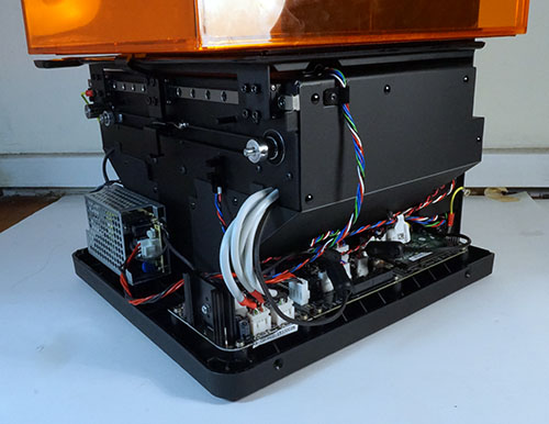
    Removing the outer shell and taking a look around, we continue to see evidence of thoughtful engineering. The cable assemblies are all labeled and color-coded; there’s comprehensive detail on chassis grounding; the EMI countermeasures are largely designed-in, as opposed to band-aided at the last minute; and the mechanical engineering got kicked up a notch.

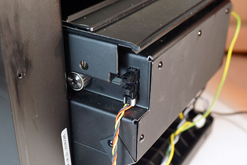
    I appreciated the inclusion of an optical limit switch on the peel drive. The previous generation’s peel mechanism relied on a mechanical clutch with a bit of overdrive, which meant every peel cycle ended with a loud clicking sound. Now, it runs much more quietly, thanks to the feedback of the limit switch.


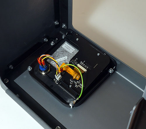
    Backside of the Form 2 LCD + touchscreen assembly.

    The touchpanel and display are mounted on the outer shell. The display is a DLC0430EZG 480×272 pixel TFT LCD employing a 24-bit RGB interface. I was a bit surprised at the use of a 30-pin ribbon cable to transmit video data between the electronics mainboard and the display assembly, as unshielded ribbon cables are notorious for unintentional RF emissions that complicate the certification process. However, a closer examination of the electronics around the ribbon cable reveal the inclusion of a CMOS-to-LVDS serdes IC on either side of the cable. Although this increases the BOM, the use of differential signaling greatly reduces the emissions footprint of the ribbon cable while improving signal integrity over an extended length of wire.

    Significantly, the capacitive touchpanel’s glass seems to be a full custom job, as indicated by the fitted shape with hole for mounting the power button. The controller IC for the touchpanel is a Tango C44 by PIXCIR, a fabless semiconductor company based out of Suzhou, China. It’s heartening to see that the market for capacitve touchpanels has commoditized to the point where a custom panel makes sense for a relatively low volume product. I remember trying to source captouch solutions back in 2008, just a couple years after the iPhone’s debut popularized capacitive multi-touch sensors. It was hard to get any vendor to return your call if you didn’t have seven figures in your annual volume estimate, and the quoted NRE for custom glass was likewise prohibitive.

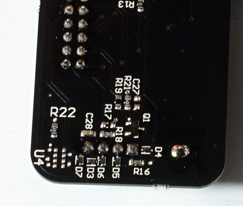
    Before leaving the touchpanel and display subsection, I have to note with a slight chuckle the two reference designators (R22 and U4) that are larger than the rest. It’s a purely cosmetic mistake which I recognize because I’ve done it myself several times. From the look of the board, I’m guessing it was designed using Altium. Automatic ECOs in Altium introduce new parts with a goofy huge default designator size, and it’s easy to miss the difference. After all, you spend most of your time editing the PCB with the silkscreen layer turned off.

    The Electronics

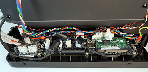
    As an electronics geek, my attention was first drawn to the electronics mainboard and the galvanometer driver board. The two are co-mounted on the right hand side of the printer, with a single 2×8 0.1” header spanning the gap between the boards. The mounting seems to be designed for easy swapping of the galvanometer board.

    I have a great appreciation for Formlabs’ choice of using a Variscite SOM (system-on-module). I can speak from first-hand experience, having designed the Novena laptop, that it’s a pain in the ass to integrate a high speed CPU, DDR3 memory, and power management into a single board with complex mixed-signal circuitry. Dropping down a couple BGA’s and routing the DDR3 fly-by topology while managing impedance and length matching is just the beginning of a long series of headaches. You then get to look forward to power sequencing, hardware validation, software drivers, factory testing, yield management and a hundred extra parts in your supply chain. Furthermore, many of the parts involved in the CPU design benefit from economies of scale much larger than can be achieved from this one product alone.

    Thus while it may seem attractive from a BOM standpoint to eliminate the middleman and integrate everything into a single PCB, from a system standpoint the effort may not amortize until the current version of the product has sold a few thousand units. By using a SOM, Formlabs reduces specialized engineering staff, saves months on the product schedule, and gains the option to upgrade their CPU without having to worry about amortization.

    Furthermore, the pitch of the CPU and DDR3 BGAs are optimized for compact designs and assume a 6 or 8-layer PCB with 3 or 4-mil design rules. If you think about it, only the 2 square inches around the CPU and DRAM require these design rules. If the entire design is just a couple square inches, it’s no big deal to fab the entire board using premium design rules. However, the Form 2’s main electronics board is about 30 square inches. Only 2 square inches of this would require the high-spec design rules, meaning they would effectively be fabricating 28 square inches of stepper motor drivers using an 8-layer PCB with 3-mil design rules. The cost to fabricate such a large area of PCB adds up quickly, and by reducing the technology requirement of the larger PCB they probably make up decent ground on the cost overhead of the SOM.

    Significantly, Formlabs was very selective about what they bought from Variscite: the SOM contained neither Wifi nor FLASH memory, even though the SOM itself had provisions for both. These two modules can be integrated onto the mainboard without driving up technology requirements, so Formlabs opted to self-source these components. In essence, they kept Variscite’s mark-up limited to a bare minimum set of components. The maturity to pick and choose cost battles is a hallmark of an engineering team with experience working in a startup environment. Engineers out of large, successful companies are used to working with virtually limitless development budgets and massive purchasing leverage, and typically show less discretion when allocating effort to cost reduction.


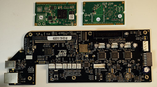
    Mainboard assembly with SOM removed; back side of SOM is photoshopped into the image for reference.

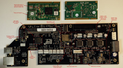
    I also like that Formlabs chose to use eMMC FLASH, instead of an SD card, for data storage. It’s probably a little more expensive, but the supply chain for eMMC is a bit more reliable than commodity SD memory. As eMMC is soldered onto the board, J3 was added to program the memory chip after assembly. It looks like the same wires going to the SOM are routed to J3, so the mainboard is probably programmed before the SOM is inserted.

    Formlabs also integrates the stepper motor drivers into the mainboard, instead of using DIP modules like the Makerbot did until at least the Replicator’s Mighty Board Rev E. I think the argument I heard for the DIP modules was serviceability; however, I have to imagine the DIP modules are problematic for thermal management. PCBs are pretty good heatsinks, particularly those with embedded ground planes. Carving up the PCB into tiny modules appreciably increases the thermal resistance between the stepper motor driver and the air around it, which might actually drive up the failure rate. The layout of the stepper motor drivers on the Formlabs mainboard show ample provisions for heat to escape the chips into the PCB through multiple vias and large copper fills.


    Mainboard assembly with annotations according to the discussion in this post.

    Overall, the mainboard was thoughtfully designed and laid out; the engineering team (or engineer) was thinking at a system-level. They managed to escape the “second system effect” by restrained prioritization of engineering effort; just because they raised a pile of money didn’t mean they had to go re-engineer all the things. I also like that the entire layout is single-sided, which simplifies assembly, inspection and testing.

    I learned a lot from reading this board. I’ve often said that reading PCBs is better than reading a textbook for learning electronics design, which is part of the reason I do a monthly Name that Ware. For example, I don’t have extensive experience in designing motor controllers, so next time I need to design a stepper motor driver, I’m probably going to have a look at this PCB for ideas and inspiration – a trivial visual inspection will inform me on what parts they used, the power architecture, trace widths, via counts, noise isolation measures and so forth. Even if the hardware isn’t Open, there’s still a lot that can be learned just by looking at the final design.

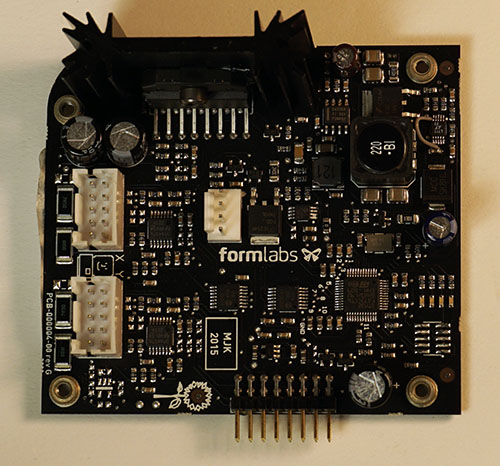
    Now, I turn my attention to the galvanometer driver board. This is a truly exciting development! The previous generation used a fully analog driver architecture which I believe is based on an off-the-shelf galvanometer driver. A quick look around this PCB reveals that they’ve abandoned closing the loop in the analog domain, and stuck a microcontroller in the signal processing path. The signal processing is done by a STM32F373 – a 72 MHz, Cortex-M4 with FPU, HW division, and DSP extensions. Further enhancing its role as a signal processing element, the MCU integrates a triplet of 16-bit sigma-delta ADCs and 12-bit DACs. The board also has a smattering of neat-looking support components, such as a MCP42010 digital potentiometer, a fairly handsome OPA4376 precision rail-to-rail op amp, and a beefy LM1876 20W audio amplifier, presumably used to drive the galvanometer voice coils.

    The power for the audio amplifier is derived from a pair of switching regulators, a TPS54336A handling the positive rail, and an LTC3704 handling the negative rail. There’s a small ECO wire on the LTC3704 which turns off burst mode operation; probably a good idea, as burst mode would greatly increase the noise on the negative rail, and in this application standby efficiency isn’t a paramount concern. I’m actually a little surprised they’re able to get the performance they need using switching regulators, but with a 20W load that may have been the only practical option. I guess the switching regulator’s frequency is also much higher than the bandwidth of the galvos, so maybe in practice the switching noise is irrelevant. There is evidence of a couple of tiny SOT-23 LDOs scattered around the PCB to clean up the supplies going to sensitive analog front-end circuitry, and there’s also this curious combination of a FQD7N10L NFET plus MPC6L02 dual op-amp. It looks like they intended the NFET to generate some heat, given the exposed solder slug on the back side, which makes me think this could be a discrete pass-FET LDO of some type. There’s one catch: the MCP6L02 can only operate at up to 6V, and power inside the Form 2 is distributed at 24V. There’s probably something clever going on here that I’m not gathering from a casual inspection of the PCBs; perhaps later I’ll break out some oscope probes to see what’s going on.

    Overall, this ground-up redesign of the galvanometer driver should give Formlabs a strong technological foundation to implement tricks in the digital domain, which sets it apart from clones that still rely upon off-the-shelf fully analog galvanometer driver solutions.

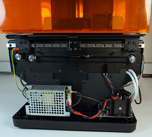
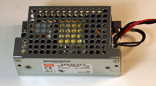
    Before leaving our analysis of the electronics, let’s not forget the main power supply. It’s a Meanwell EPS-65-24-C. The power supply itself isn’t such a big deal, but the choice to include it within the chassis is interesting. Many, if not most, consumer electronic devices prefer to use external power bricks because it greatly simplifies certification. Devices that use voltages below 60V fall into the “easy” category for UL and CE certification. By pulling the power supply into the chassis, they are running line voltages up to 240V inside, which means they have to jump through IEC 60950-1 safety testing. It ups the ante on a number of things, including the internal wiring standards and the flame retardance of any plastics used in the assembly. I’m not sure why they decided to pull the power supply into the chassis; they aren’t using any fancy point-of-load voltage feedback to cancel out IR drops on the cable. My best guess is they felt it would either be a better customer experience to not have to deal with an external power brick, or perhaps they were bitten in the previous generation by flaky power bricks or ground loop/noise issues that sometimes plague devices that use external AC power supplies.

    The Mechanical Platform

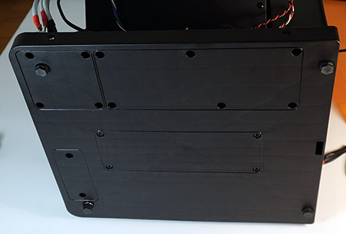
    It turns out that my first instinct to rip out the electronics was probably the wrong order for taking apart the Form 2. A closer inspection of the base reveals a set of rounded rectangles that delineate the screws belonging to each physical subsystem within the device. This handy guide makes assembly (and repair) much easier.

    The central set of screws hold down the mechanical platform. Removing those causes the whole motor and optics assembly to pop off cleanly, giving unfettered access to all the electronics.

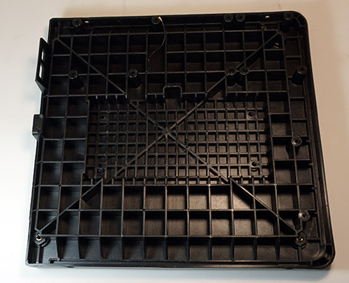
    I’m oddly excited about the base of the Form 2. It looks like just a humble piece of injection molded plastic. But this is an injection molded piece of plastic designed to withstand the apocalypse. Extensive ribbing makes the base extremely rigid, and resistant to warpage. The base is also molded using glass-filled polymer – the same tough stuff used to make Pelican cases and automotive engine parts. I’ve had the hots for glass-filled polymers recently, and have been itching for an excuse to use it in one of my designs. Glass-filled polymer isn’t for happy-meal toys or shiny gadgets, it’s tough stuff for demanding applications, and it has an innately rugged texture. I’m guessing they went for a bomb-proof base because anything less rigid would lead to problems keeping the resin tank level. Either that, or someone in Formlabs has the same fetish I have for glass filled polymers.

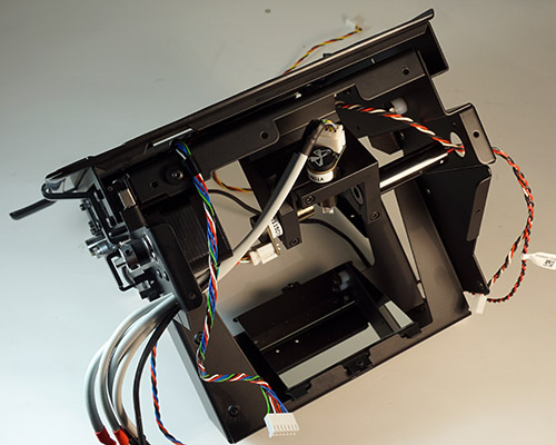
    Once removed from the base, the central mechanical chassis stands upright on its own. Inside this assembly is the Z-axis leadscrew for the build platform, resin level sensor, resin heater, peel motor, resin stirrer, and the optics engine.

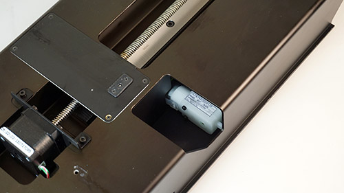
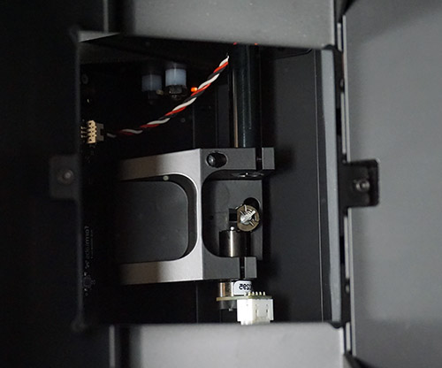
    Here’s a close-up of the Z-stepper motor + leadscrew, resin level & temperature sensor, and resin valve actuator. The resin valve actuator is a Vigor Precision BO-7 DC motor with gearbox, used to drive a swinging arm loaded with a spring to provide the returning force. The arm pushes on the integral resin cartridge valve, which looks uncannily like the bite valve from a Camelback.

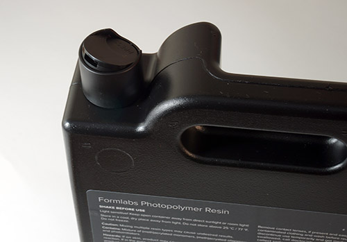
    The resin tank valve is complimented by the resin tank’s air vent, which also looks uncannily like the top of a shampoo bottle.

    My guess is Formlabs is either buying these items directly from the existing makers of Camelback and shampoo products, in which case First Sale Doctrine means any patent claims that may exist on these has been exhausted, or they have licensed the respective IP to make their own version of each.

    The resin level and temperature sensor assembly is also worth a closer look. It’s a PCB that’s mounted directly behind the resin tank, and in front of the Z-motor leadscrew.


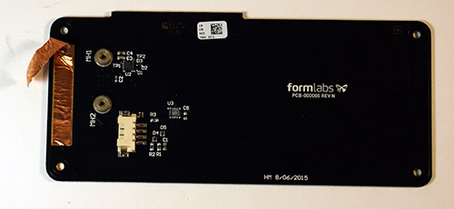
    Backside of the PCB mounted directly behind the resin tank.

    It looks like resin level is measured using a TI FDC1004 capacitive liquid level sensor. I would have thought that capacitive sensing would be too fussy for accurate liquid level sensing, but after reading the datasheet for the FDC1004 I’m a little less skeptical. However, I imagine the sensor is extremely sensitive to all kinds of contamination, the least of which is resin splattered or dripped onto the sensor PCB.


    Detail of the sensor PCB highlighting the non-contact thermopile temperature sensor.

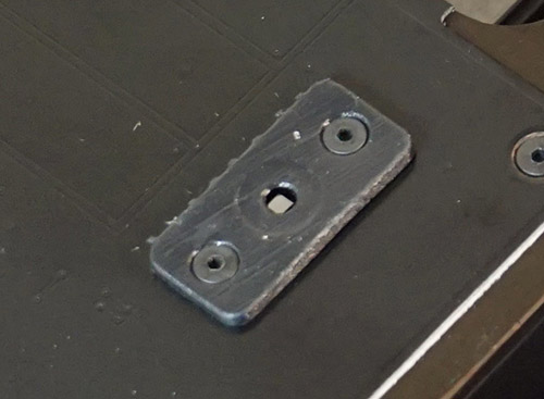
    The resin temperature sense mechanism is also quite interesting. You’ll note a little silvery square, shrouded in plastic, mounted on the PCB behind the resin tank. First of all, the plastic shroud on my unit is clearly a 3D printed piece done by another Formlabs printer. You can see the nubs from the support structure and striation artifacts from the buildup process. I love that they’re dogfooding and using their own products to prototype and test; it’s a bad sign if the engineering team doesn’t believe in their own product enough to use it themselves.

    Unscrewing the 3D printed shroud reveals a curious flip-chip CSP device, which I’m guessing is a TI TMP006 or TMP007 MEMS therompile. Although there are no part numbers on the chip, a quick read through the datasheet reveals a reference layout that is a dead ringer for the pattern on the PCB around the chip. Thermopiles can do non-contact remote temperature sensing, and it looks like this product has an accuracy of about +/-1 C between 0-60C. This explains the mystery of how they’re able to report the resin temperature on the UI without any sort of probe dipping into the resin tank.

    But then how do they heat it? Look under the resin tank mount, and we find another PCB.

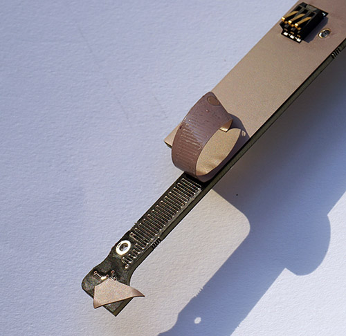
    When I first saw this board, I thought its only purpose was to hold the leafspring contacts for the ID chip that helps track individual resin tanks and what color resin was used in them. Flip the PCB over, and you’ll see a curious pinkish tape covering the reverse surface.

    The pinkish tape is actually a thermal gap sealer, and peeling the tape back reveals that the PCB itself has a serpentine trace throughout, which means they are using the resistivity of the copper trace on the PCB itself as a heating mechanism for the resin.

    Again, I wouldn’t have guessed this is something that would work as well as it does, but there you have it. It’s a low-cost mechanism for controlling the temperature of the resin during printing. Probably the PCB material is the most expensive component, even more than the thermopile IR sensor, and all that’s needed to drive the heating element is a beefy BUK9277 NFET.

    I’ve been to the Formlabs offices in Boston, and it does get rather chilly and dry there in the winter, so it makes sense they would consider cold temperature as a variable that could cause printing problems on the Form 2.

    Cold weather isn’t a problem here in Singapore; however, persistent 90% humidity conditions is an issue. If I didn’t use my Form 1 for several weeks, the first print would always come out badly; usually I’d have to toss the resin in the tank and pour a fresh batch for the print to come out. I managed to solve this problem by placing a large pack of desiccant next to the resin tank, as well as using the shipping lid to try to seal out moisture. However, I’m guessing they have very few users in the tropics, so humidity-related print problems are probably going to be a unique edge case I’ll have to solve on my own for some time to come.

    The Optics Pathway

    Finally, the optics – I’m saving the best for last. The optics pathway is the beating heart of the Form 2.


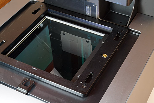
    The last thing uncured resin sees before it turns into plastic.

    The first thing I noticed about the optics is the inclusion of a protective glass panel underneath the resin tank. In the Form 1, if the build platform happened to drip resin while the tank was removed, or if the room was dusty, you had the unenviable task of reaching into the printer to clean the mirror. The glass panel simplifies the cleaning operation while protecting sensitive optics from dust and dirt.

    I love that the protective glass has an AR coating. You can tell there’s an AR coating from the greenish tint of the reflections off the surface of the glass. AR coatings are sexy; if I had a singles profile, you’d see “the green glint of AR-coated glasses” under turn-ons. Of course, the coating is there for functional reasons – any loss of effective laser power due to reflections off of the protective glass would reduce printing efficiency.

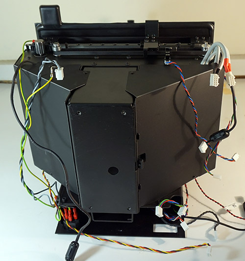
    The contamination-control measures don’t just stop at a protective glass cover. Formlabs also provisioned a plastic shroud around the entire optics assembly.


    Bottom view of the mechanical platform showing the protective shrouds hiding the optics.

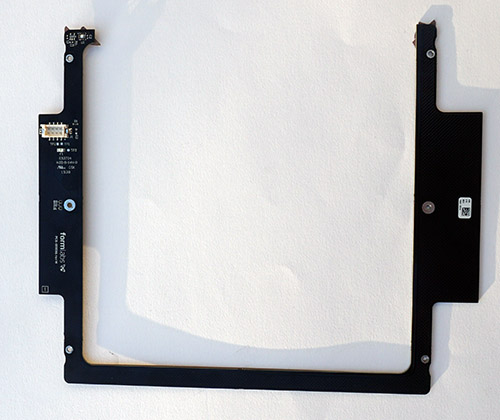
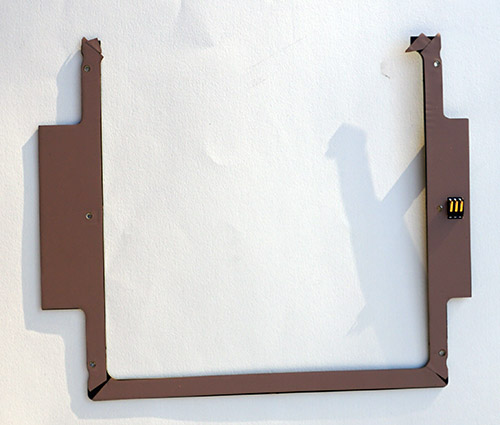
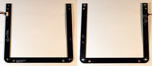
    Immediately underneath the protective glass sheet is a U-shaped PCB which I can only assume is used for some kind of calibration. The PCB features five phtoodetectors; one mounted in “plain sight” of the laser, and four mounted in the far corners on the reverse side of the PCB, with the detectors facing into the PCB, such that the PCB is obscuring the photodetectors. A single, small pinhole located in the center of each detector allows light to fall onto the obscured photodetectors. However, the size of the pinhole and the dimensional tolerance of the PCB is probably too large for this to be an absolute calibration for the printer. My guess is this is probably used as more of a coarse diagnostic to confirm laser power and range of motion of the galvanometers.

    Popping off the shroud reveals the galvanometer and laser assembly. The galvanometers sport a prominent Formlabs logo. They are a Formlabs original design, and not simply a relabeling of an off the shelf solution. This is a really smart move, especially in the face of increasing pressure from copycats. Focusing resources into building a proprietary galvo is a trifecta for Formlabs: they get distinguished print quality, reduced cost, and a barrier to competition all in one package. Contrast this to Formlabs’ decision to use a SOM for the CPU; if Formlabs can build their own galvo & driver board, they certainly had the technical capability to integrate a CPU into the mainboard. But in terms of priorities, improving the galvo is a much better payout.

    Readers unfamiliar with galvanometers may want to review a Name that Ware I did of a typical galvanometer a while back. In a nutshell, a typical galvanometer consists of a pair of voice coils rotating a permanent magnet affixed to a shaft. The shaft’s angle is measured by an optical feedback system, where a single light source shines onto a paddle affixed to the galvo’s shaft. The paddle alternately occludes light hitting a pair of photodetectors positioned behind the paddle relative to the light source.

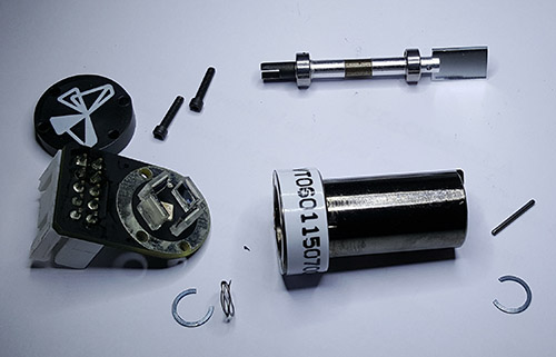
    Now, here’s the entire Form 2 galvo assembly laid out in pieces.


    Close-up view of the photoemitter and detector arrangement.

    Significantly, the Form 2 galvo has not two, but four photodetectors, surrounding a single central light source. Instead of a paddle, a notch is cut into the shaft; the notch modulates the light intensity reaching the photodiodes surrounding the central light source according to the angle of the shaft.


    The notched shaft above sits directly above the photoemitter when the PCB is mated to the galvo body.

    This is quite different from the simple galvanometer I had taken apart previously. I don’t know enough about galvos to recognize if this is a novel technique, or what exactly is the improvement they hoped to get by using four photodiodes instead of two. With two photodiodes, you get to subtract out the common mode of the emitter and you’re left with the error signal representing the angle of the shaft: two variables solving for two unknowns. With four photodiodes, they can solve for a couple more unknowns – but what are they? Maybe they are looking to correct for alignment errors of the light source & photodetectors relative to the shaft, wobble due to imperfections in the bearings, or perhaps they’re trying to avoid a dead-spot in the response of the photodiodes as the shaft approaches the extremes of rotation. Or perhaps the explanation is as simple as removing the light-occluding paddle reduces the mass of the shaft assembly, allowing it to rotate faster, and four photodetectors was required to produce an accurate reading out of a notch instead of the paddle. When I reached out to Formlabs to ask about this, someone in the know responded that the new design is an improvement on three issues: more signal leading to an improved SNR, reduced impact of off-axis shaft motion, and reduced thermal drift due to better symmetry.

    This is the shaft plus bearings once it’s pulled out of the body of the galvo. The gray region in the middle is the permanent magnet, and it’s very strong.

    And this is staring back into the galvo with the shaft removed. You can see the edges of the voice coils. I couldn’t remove them from the housing, as they seem to be fixed in place with some kind of epoxy.

    Epilogue
    And there you have it – the Form 2, from taking off its outer metal case down to the guts of its galvanometers. It was a lot of fun tearing down the Form2, and I learned a lot while doing it. I hope you also enjoyed reading this post, and perhaps gleaned a couple useful bits of knowledge along the way.

    If you think Formlabs is doing cool stuff and solving interesting problems, good news: they’re hiring! They have new positions for a Software Lead and an Electrical Systems Lead. Follow the links for a detailed description and application form.

    Sex, Circuits & Deep House

    Monday, September 28th, 2015

    P9010002
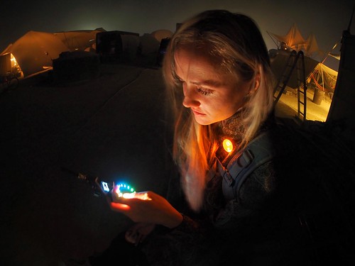
    Cari with the Institute Blinky Badge at Burning Man 2015. Photo credit: Nagutron.

    This year for Burning Man, I built a networked light badge for my theme camp, “The Institute”. Walking in the desert at night with no light is a dangerous proposition – you can get run over by cars, bikes, or twist an ankle tripping over an errant bit of rebar sticking out of the ground. Thus, the outrageous, bordering grotesque, lighting spectacle that Burning Man becomes at night grows out of a central need for safety in the dark. While a pair of dimly flashing red LEDs should be sufficient to ensure one’s safety, anything more subtle than a Las Vegas strip billboard tends to go unnoticed by fast-moving bikers thanks to the LED arms race that has become Burning Man at night.

    I wanted to make a bit of lighting that my campmates could use to stay safe – and optionally stay classy by offering a range of more subtle lighting effects. I also wanted the light patterns to be individually unique, allowing easy identification in dark, dusty nights. However, diddling with knobs and code isn’t a very social experience, and few people bring laptops to Burning Man. I wanted to come up with a way for people to craft an identity that was inherently social and interactive. In an act of shameless biomimicry, I copied nature’s most popular protocol for creating individuals – sex.

    By adding a peer-to-peer radio in each badge, I was able to implement a protocol for the breeding of lighting patterns via sex.


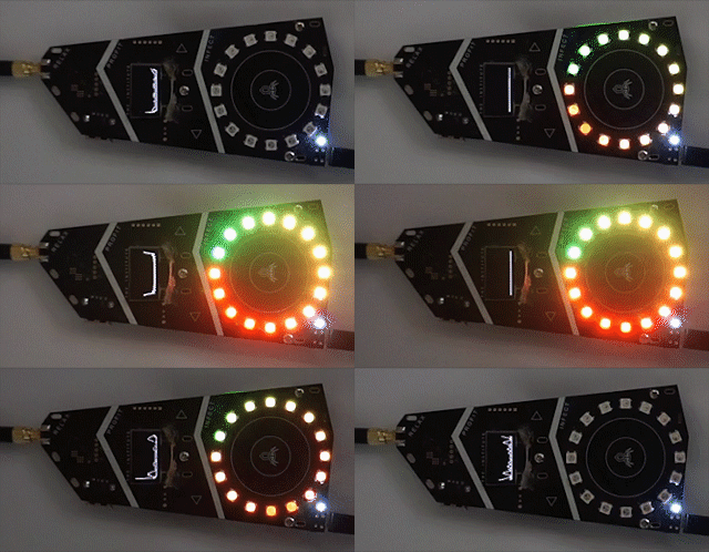
    Some examples of the unique light patterns possible through sex.

    Sex

    When most people think of sex, what they are actually thinking about is sexual intercourse. This is understandable, as technology allows us to have lots of sexual intercourse without actually accomplishing sexual reproduction. Still, the double-entendre of saying “Nice lights! Care to have sex?” is a playful ice breaker for new interactions between camp mates.

    Sex, in this case, is used to breed the characteristics of the badge’s light pattern as defined through a virtual genome. Things like the color range, blinking rate, and saturation of the light pattern are mapped into a set of diploid (two copies of each gene) chromosomes (code) (spec). Just as in biological sex, a badge randomly picks one copy of each gene and packages them into a sperm and an egg (every badge is a hermaphrodite, much like plants). A badge’s sperm is transmitted wirelessly to another host badge, where it’s mixed with the host’s egg and a new individual blending traits of both parents is born. The new LED pattern replaces the current pattern on the egg donor’s badge.

    Biological genetic traits are often analog, not digital – height or weight are not coded as discrete values in a genome. Instead, observed traits are the result of a complex blending process grounded in the minutiae of metabolic pathways and the efficacy of enzymes resulting from the DNA blueprint and environment. The manifestation of binary situations like recessive vs. dominant is often the result of a lot of gain being applied to an analog signal, thus causing the expressed trait to saturate quickly if it’s expressed at all.

    In order to capture the wonderful diversity offered by sex, I implement quantitative traits in the light genome. Instead of having a single bit for each trait, it’s a byte, and there’s an expression function that combines the values from each gene (alleles) to derive a final observed trait (phenotype).

    By carefully picking expression functions, I can control how the average population looks. Let’s consider saturation (I used an HSV colorspace, instead of RGB, which makes it much easier to create aesthetically pleasing color combinations). A highly saturated color is vivid and bright. A less saturated color appears pastel, until finally it’s washed out and looks just white or gray (a condition analogous to albinism).

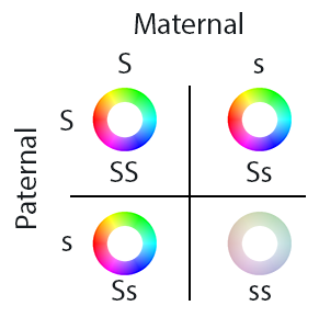
    If I want albinism to be rare, and bright colors to be common, the expression function could be a saturating add. Thus, even if one allele (copy of the gene) has a low value, the other copy just needs to be a modest value to result in a bright, vivid coloration. Albinism only occurs when both copies have a fairly low value.


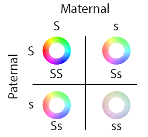
    Population makeup when using saturating addition to combine the maternal and paternal saturation values. Albinism – a badge light pattern looking white or gray – happens only when both maternal and paternal values are small. ‘S’ means large saturation, and ‘s’ means little saturation. ‘SS’ and ‘Ss’ pairings of genes leads to saturated colors, while only the ‘ss’ combination leads to a net low saturation (albinism).

    On the other hand, if I wanted the average population to look pastel, I can simply take the average of each allele, and take that to be the saturation value. In this case, a bright color can only be achieved in both alleles have a high value. Likewise, an albino can only be achieved if both alleles have a low value.


    Population makeup when using averaging to combine the maternal and paternal saturation values. The most common case is a pastel palette, with vivid colors and albinism both suppressed in the population.

    For Burning Man, I chose saturating addition as the expression function, to have the population lean toward vivid colors. I implemented other features such as cyclic dimming, hue rotation, and color range using similar techniques.

    It’s important when thinking about biological genes to remember that they aren’t like lines of computer code. Rather, they are like the knobs on an analog synth, and the resulting sound depends not just on the position of the knob, but where it is in the signal chain how it interacts with other effects.

    Gender and Consent

    Beyond genetics, there is a minefield of thorny decisions to be made when implementing the social policies and protocols around sex. What are the gender roles? And what about consent? This is where technology and society collide, making for a fascinating social experiment.

    I wanted everyone to have an opportunity to play both gender roles, so I made the badges hermaphroditic, in the sense that everyone can give or receive genetic material. The “maternal” role receives sperm, combines it with an egg derived from the currently displayed light pattern, and replaces its light pattern with a new hybrid of both. The “paternal” role can transmit a sperm derived from the currently displayed pattern. Each badge has the requisite ports to play both roles, and thus everyone can play the role of male or female simply by being either the originator of or responder to a sex request.

    This leads us to the question of consent. One fundamental flaw in the biological implementation of sex is the possibility of rape: operating the hardware doesn’t require mutual consent. I find the idea of rape disgusting, even if it’s virtual, so rape is disallowed in my implementation. In other words, it’s impossible for a paternal badge to force a sperm into a maternal badge: male roles are not allowed to have sex without first being asked by a female role. Instead, the person playing the female role must first initiate sex with a target mate. Conversely, female roles can’t steal sperm from male roles; sperm is only generated after explicit consent from the male. Assuming consent is given, a sperm is transmitted to the maternal badge and the protocol is complete. This two-way handshake assures mutual consent.

    This non-intuitive and partially role-reversed implementation of sex lead to users asking support questions akin to “I’m trying to have sex, but why am I constantly being denied?” and my response was – well, did you ask your potential mate if it was okay to have sex first? Ah! Consent. The very important but often overlooked step before sex. It’s a socially awkward question, but with some practice it really does become more natural and easy to ask.

    Some users were enthusiastic early adopters of explicit consent, while others were less comfortable with the question. It was interesting to see the ways straight men would ask other straight men for sex – they would ask for “ahem, blinky sex” – and anecdotally women seemed more comfortable and natural asking to have sex (regardless of the gender of the target user).

    As an additional social experiment, I introduced a “rare” trait (pegged at ~3% of a randomly generated population) consisting of a single bright white pixel that cycles around the LED ring. I wanted to see if campmates would take note and breed for the rare trait simply because it’s rare. At the end of the week, more people were expressing the rare phenotype than at the beginning, so presumably some selective breeding for the trait did happen.

    In the end, I felt that having sex to breed interesting light patterns was a lot more fun for everyone than tweaking knobs and sliders in a UI. Also, because traits are inherited through sexual reproduction, by the end of the event one started to see families of badges gaining similar traits, but thanks to the randomness inherent in sex you could still tell individuals apart in the dark by their light patterns.

    Finding Friends

    Implementing sex requires a peer-to-peer radio. So why not also use the radio to help people locate nearby friends? Seems like a good idea on the outside, but the design of this system is a careful balance between creating a general awareness of friends in the area vs. creating a messaging client.

    Personally, one of the big draws of going to Burning Man is the ability to unplug from the Internet and live in an environment of intimate immediacy – if you’re physically present, you get 100% of my attention; otherwise, all bets are off. Email, SMS, IRC, and other media for interaction (at least, I hear there are others, but I don’t use them…) are great for networking and facilitating business, but they detract from focusing on the here and now. For me there’s something ironic about seeing a couple in a fancy restaurant, both hopelessly lost staring deeply into their smartphones instead of each other’s eyes. Being able to set an auto-responder for two weeks which states that your email will never be read is pretty liberating, and allows me to open my mind up to trains of thought that can take days to complete. Thus, I really wanted to avoid turning the badge into a chat client, or any sort of communication medium that sets any expectation of reading messages and responding in a timely fashion.

    On the other hand, meeting up with friends at Burning Man is terribly hard. It’s life before the cell phone – if you’re old enough to remember that. Without a cell phone, you have a choice between enjoying the music, stalking around the venue to find friends, or dancing in one spot all night long so you’re findable. Simply knowing if my friends have finally showed up is a big help; if they haven’t arrived yet, I can get lost in the music and check out the sound in various parts of the venue until they arrive.

    Thus, I designed a very simple protocol which will only reveal if your friends are nearby, and nothing else. Every badge emits a broadcast ping every couple of seconds. Ideally, I’d use an RSSI (receive signal strength indicator) to figure out how far the ping is, but due to a quirk of the radio hardware I was unable to get a reliable RSSI reading. Instead, every badge would listen for the pings, and decrement the ping count at a slightly slower average rate than the ping broadcast. Thus, badges solidly within radio range would run up a ping count, and as people got farther and farther away, the ping count would decrease as pings gradually get lost in the noise.


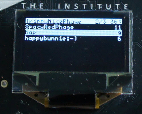
    Friend finding UI in action. In this case, three other badges are nearby, SpacyRedPhage, hap, and happybunnie:-). SpacyRedPhage is well within range of the radio, and the other two are farther away.

    The system worked surprisingly well. The reliable range of the radio worked out to be about 200m in practice, which is about the sound field of a major venue at Burning Man. It was very handy for figuring out if my friends had left already for the night, or if they were still prepping at camp; and there was one memorable reunion at sunrise where a group of my camp mates drove our beloved art car, Dr. Brainlove, to Robot Heart and I was able to quickly find them thanks to my badge registering a massive amount of pings as they drove into range.

    Hardware Details

    I’m not so lucky that I get to design such a complex piece of hardware exclusively for a pursuit as whimsical as Burning Man. Rather, this badge is a proof-of concept of a larger effort to develop a new open-source platform for networked embedded computers (please don’t call it IoT) backed by a rapid deployment supply chain. Our codename for the platform is Orchard.

    The Burning Man badge was our first end-to-end test of Orchard’s “supply chain as a service” concept. The core reference platform is fairly well-documented here, and as you can see looks nothing like the final badge.


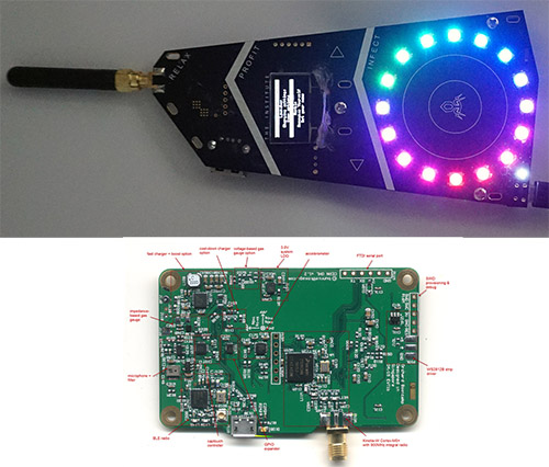
    Bottom: orchard reference design; top: orchard variant as customized for Burning Man.

    However, the only difference at a schematic level between the reference platform and the badge is the addition of 14 extra RGB LEDs, the removal of the BLE radio, and redesign of the captouch electrode pattern. Because the BOM of the badge is a strict subset of the reference design, we were able to go from a couple prototypes in advance of a private Crowd Supply campaign to 85 units delivered at the door of camp mates in about 2.5 months – and the latency of shipping units from China to front doors in the US accounts for one full month of that time.


    The badge sports an interactive captouch surface, an OLED display, 900MHz ISM band peer-to-peer radio, microphone, accelerometer, and more!

    If you’re curious, you can view documentation about the Orchard platform here, and discuss it at the Kosagi forum.

    Reflection

    As an engineer, my “default” existence is confined on four sides by cost, schedule, quality, and specs, with a sprinkling of legal, tax, and regulatory constraints on top. It’s pretty easy to lose your creative spark when every day is spent threading the needle of profit and loss.

    Even though the implementation of Burning Man’s principles of decommodification and gifting is far from perfect, it’s sufficient to enable me to loosen the shackles of my daily existence and play with technology as a medium for enhancing human interactions, and not simply as a means for profit. In other words, thanks to the values of the community, I’m empowered and supported to build stuff that wouldn’t make sense for corporate shareholders, but might improve the experiences of my closest friends. I think this ability to leave daily existence behind for a couple weeks is important for staying balanced and maintaining perspective, because at least for me maximizing profit is rarely the same as maximizing happiness. After all, a warm smile and a heartfelt hug is priceless.

    From Gongkai to Open Source

    Monday, December 29th, 2014

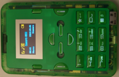
    About a year and a half ago, I wrote about a $12 “Gongkai” cell phone (pictured above) that I stumbled across in the markets of Shenzhen, China. My most striking impression was that Chinese entrepreneurs had relatively unfettered access to cutting-edge technology, enabling start-ups to innovate while bootstrapping. Meanwhile, Western entrepreneurs often find themselves trapped in a spiderweb of IP frameworks, spending more money on lawyers than on tooling. Further investigation taught me that the Chinese have a parallel system of traditions and ethics around sharing IP, which lead me to coin the term “gongkai”. This is deliberately not the Chinese word for “Open Source”, because that word (kaiyuan) refers to openness in a Western-style IP framework, which this not. Gongkai is more a reference to the fact that copyrighted documents, sometimes labeled “confidential” and “proprietary”, are made known to the public and shared overtly, but not necessarily according to the letter of the law. However, this copying isn’t a one-way flow of value, as it would be in the case of copied movies or music. Rather, these documents are the knowledge base needed to build a phone using the copyright owner’s chips, and as such, this sharing of documents helps to promote the sales of their chips. There is ultimately, if you will, a quid-pro-quo between the copyright holders and the copiers.
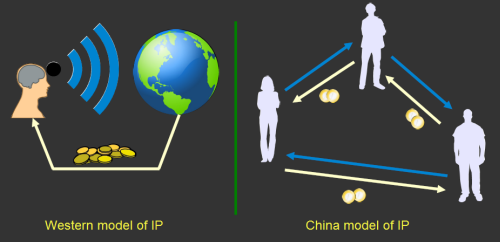
    This fuzzy, gray relationship between companies and entrepreneurs is just one manifestation of a much broader cultural gap between the East and the West. The West has a “broadcast” view of IP and ownership: good ideas and innovation are credited to a clearly specified set of authors or inventors, and society pays them a royalty for their initiative and good works. China has a “network” view of IP and ownership: the far-sight necessary to create good ideas and innovations is attained by standing on the shoulders of others, and as such there is a network of people who trade these ideas as favors among each other. In a system with such a loose attitude toward IP, sharing with the network is necessary as tomorrow it could be your friend standing on your shoulders, and you’ll be looking to them for favors. This is unlike the West, where rule of law enables IP to be amassed over a long period of time, creating impenetrable monopoly positions. It’s good for the guys on top, but tough for the upstarts.

    This brings us to the situation we have today: Apple and Google are building amazing phones of outstanding quality, and start-ups can only hope to build an appcessory for their ecosystem. I’ve reviewed business plans of over a hundred hardware startups by now, and most of them are using overpriced chipsets built using antiquated process technologies as their foundation. I’m no exception to this rule – we use the Freescale i.MX6 for Novena, which is neither the cheapest nor the fastest chip on the market, but it is the one chip where anyone can freely download almost complete documentation and anyone can buy it on Digikey. This parallel constraint of scarce documentation and scarce supply for cutting edge technology forces Western hardware entrepreneurs to look primarily at Arduino, Beaglebone and Raspberry Pi as starting points for their good ideas.
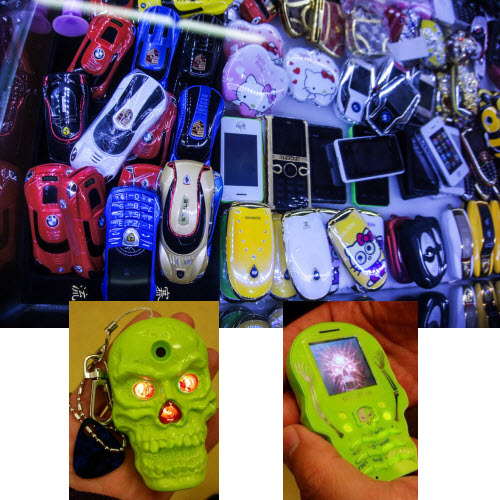

    Above: Every object pictured is a phone. Inset: detail of the “Skeleton” novelty phone. Image credits: Halfdan, Rachel Kalmar

    Chinese entrepreneurs, on the other hand, churn out new phones at an almost alarming pace. Phone models change on a seasonal basis. Entrepreneurs experiment all the time, integrating whacky features into phones, such as cigarette lighters, extra-large battery packs (that can be used to charge another phone), huge buttons (for the visually impaired), reduced buttons (to give to children as emergency-call phones), watch form factors, and so forth. This is enabled because very small teams of engineers can obtain complete design packages for working phones – case, board, and firmware – allowing them to fork the design and focus only on the pieces they really care about.

    As a hardware engineer, I want that. I want to be able to fork existing cell phone designs. I want to be able to use a 364 MHz 32-bit microcontroller with megabytes of integrated RAM and dozens of peripherals costing $3 in single quantities, instead of a 16 MHz 8-bit microcontroller with a few kilobytes of RAM and a smattering of peripherals costing $6 in single quantities. Unfortunately, queries into getting a Western-licensed EDK for the chips used in the Chinese phones were met with a cold shoulder – our volumes are too small, or we have to enter minimum purchase agreements backed by hundreds of thousands of dollars in a cash deposit; and even then, these EDKs don’t include all the reference material the Chinese get to play with. The datasheets are incomplete and as a result you’re forced to use their proprietary OS ports. It feels like a case of the nice guys finishing last. Can we find a way to still get ahead, yet still play nice?

    We did some research into the legal frameworks and challenges around absorbing Gongkai IP into the Western ecosystem, and we believe we’ve found a path to repatriate some of the IP from Gongkai into proper Open Source. However, I must interject with a standard disclaimer: we’re not lawyers, so we’ll tell you our beliefs but don’t construe them as legal advice. Our intention is to exercise our right to reverse engineer in a careful, educated fashion to increase the likelihood that, if push comes to shove, the courts will agree with our actions. However, we also feel that shying away from reverse engineering simply because it’s controversial is a slippery slope: you must exercise your rights to have them. If women didn’t vote and black people sat in the back of the bus because they were afraid of controversy, the US would still be segregated and without universal suffrage.

    Sometimes, you just have to stand up and assert your rights.

    There are two broad categories of issues we have to deal with, patents and copyrights. For patents, the issues are complex, yet it seems the most practical approach is to essentially punt on the issue. This is what the majority of the open source community does, and in fact many corporations have similar policies at the engineering level. Nobody, as far as we know, checks their Linux commits for patent infringement before upstreaming them. Why? Among other reasons, it takes a huge amount of resources to determine which patents apply, and if one could be infringing; and even after expending those resources, one cannot be 100% sure. Furthermore, if one becomes very familiar with the body of patents, it amplifies the possibility that an infringement, should it be found, is willful and thus triple damages. Finally, it’s not even clear where the liability lies, particularly in an open source context. Thus, we do our best not to infringe, but cannot be 100% sure that no one will allege infringement. However, we do apply a license to our work which has a “poison pill” clause for patent holders that do attempt to litigate.

    For copyrights, the issue is also extremely complex. The EFF’s Coders’ Rights Project has a Reverse Engineering FAQ that’s a good read if you really want to dig into the issues. The tl;dr is that courts have found that reverse engineering to understand the ideas embedded in code and to achieve interoperability is fair use. As a result, we have the right to study the Gongkai-style IP, understand it, and produce a new work to which we can apply a Western-style Open IP license. Also, none of the files or binaries were encrypted or had access controlled by any technological measure – no circumvention, no DMCA problem.

    Furthermore, all the files were obtained from searches linking to public servers – so no CFAA problem, and none of the devices we used in the work came with shrink-wraps, click-throughs, or other end-user license agreements, terms of use, or other agreements that could waive our rights.

    Thus empowered by our fair use rights, we decided to embark on a journey to reverse engineer the Mediatek MT6260. It’s a 364 MHz, ARM7EJ-S, backed by 8MiB of RAM and dozens of peripherals, from the routine I2C, SPI, PWM and UART to tantalizing extras like an LCD + touchscreen controller, audio codec with speaker amplifier, battery charger, USB, Bluetooth, and of course, GSM. The gray market prices it around $3/unit in single quantities. You do have to read or speak Chinese to get it, and supply has been a bit spotty lately due to high Q4 demand, but we’re hoping the market will open up a bit as things slow down for Chinese New Year.

    For a chip of such complexity, we don’t expect our two-man team to be able to unravel its entirety working on it as a part-time hobby project over the period of a year. Rather, we’d be happy if we got enough functionality so that the next time we reach for an ATMega or STM32, we’d also seriously consider the MT6260 as an alternative. Thus, we set out as our goal to port NuttX, a BSD-licensed RTOS, to the chip, and to create a solid framework for incrementally porting drivers for the various peripherals into NuttX. Accompanying this code base would be original hardware schematics, libraries and board layouts that are licensed using CC BY-SA-3.0 plus an Apache 2.0 rider for patent issues.

    And thus, the Fernvale project was born.

    Fernvale Hardware

    Compared to the firmware, the hardware reverse engineering task was fairly straightforward. The documents we could scavenge gave us a notion of the ball-out for the chip, and the naming scheme for the pins was sufficiently descriptive that I could apply common sense and experience to guess the correct method for connecting the chip. For areas that were ambiguous, we had some stripped down phones I could buzz out with a multimeter or stare at under a microscope to determine connectivity; and in the worst case I could also probe a live phone with an oscilloscope just to make sure my understanding was correct.

    The more difficult question was how to architect the hardware. We weren’t gunning to build a phone – rather, we wanted to build something a bit closer to the Spark Core, a generic SoM that can be used in various IoT-type applications. In fact, our original renderings and pin-outs were designed to be compatible with the Spark ecosystem of hardware extensions, until we realized there were just too many interesting peripherals in the MT6260 to fit into such a small footprint.
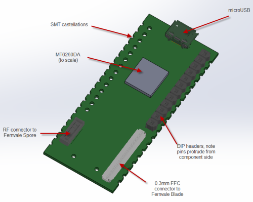
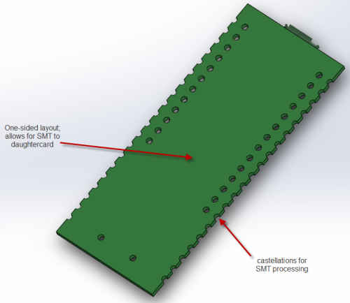
    Above: early sketches of the Fernvale hardware

    We settled eventually upon a single-sided core PCB that we call the “Fernvale Frond” which embeds the microUSB, microSD, battery, camera, speaker, and Bluetooth functionality (as well as the obligatory buttons and LED). It’s slim, at 3.5mm thick, and at 57x35mm it’s also on the small side. We included holes to mount a partial set of pin headers, spaced to be compatible with an Arduino, although it can only be plugged into 3.3V-compatible Arduino devices.


    Above: actual implementation of Fernvale, pictured with Arduino for size reference

    The remaining peripherals are broken out to a pair of connectors. One connector is dedicated to GSM-related signals; the other to UI-related peripherals. Splitting GSM into a module with many choices for the RF front end is important, because it makes GSM a bona-fide user-installed feature, thus pushing the regulatory and emissions issue down to the user level. Also, splitting the UI-related features out to another board costs down the core module, so it can fit into numerous scenarios without locking users into a particular LCD or button arrangement.
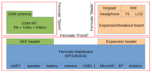

    Above: Fernvale system diagram, showing the features of each of the three boards
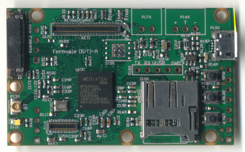

    Fernvale Frond mainboard
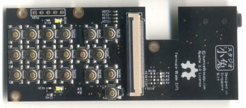

    Fernvale blade UI breakout
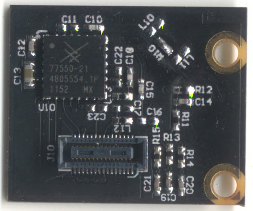

    Fernvale spore AFE dev board

    All the hardware source documents can be downloaded from our wiki.

    As an interesting side-note, I had some X-rays taken of the MT6260. We did this to help us identify fake components, just in case we encountered units being sold as empty epoxy blocks, or as remarked versions of other chips (the MT6260 has variants, such as the -DA and the -A, the difference being how much on-chip FLASH is included).
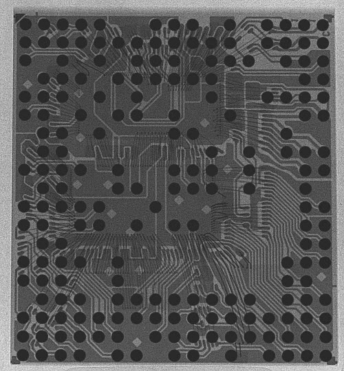

    X-ray of the MT6260 chip. A sharp eye can pick out the outline of multiple ICs among the wirebonds. Image credit: Nadya Peek

    To our surprise, this $3 chip didn’t contain a single IC, but rather, it’s a set of at least 4 chips, possibly 5, integrated into a single multi-chip module (MCM) containing hundreds of wire bonds. I remember back when the Pentium Pro’s dual-die package came out. That sparked arguments over yielded costs of MCMs versus using a single bigger die; generally, multi-chip modules were considered exotic and expensive. I also remember at the time, Krste Asanović, then a professor at the MIT AI Lab now at Berkeley, told me that the future wouldn’t be system on a chip, but rather “system mostly on a chip”. The root of his claim is that the economics of adding in mask layers to merge DRAM, FLASH, Analog, RF, and Digital into a single process wasn’t favorable, and instead it would be cheaper and easier to bond multiple die together into a single package. It’s a race between the yield and cost impact (both per-unit and NRE) of adding more process steps in the semiconductor fab, vs. the yield impact (and relative reworkability and lower NRE cost) of assembling modules. Single-chip SoCs was the zeitgeist at the time (and still kind of is), so it’s interesting to see a significant datapoint validating Krste’s insight.

    Reversing the Boot Structure

    The amount of documentation made available to Shanzhai engineers in China seems to be just enough to enable them to assemble a phone and customize its UI, but not enough to do a full OS port. You eventually come to recognize that all the phones based on a particular chipset have the same backdoor codes, and often times the UI is inconsistent with the implemented hardware. For example, the $12 phone mentioned at the top of the post will prompt you to plug headphones into the headphone jack for the FM radio to work, yet there is no headphone jack provided in the hardware. In order to make Fernvale accessible to engineers in the West, we had to reconstruct everything from scratch, from the toolchain, to the firmware flashing tool, to the OS, to the applications. Given that all the Chinese phone implementations simply rely upon Mediatek’s proprietary toolchain, we had to do some reverse engineering work to figure out the boot process and firmware upload protocol.

    My first step is always to dump the ROM, if possible. We found exactly one phone model which featured an external ROM that we could desolder (it uses the -D ROMless variant of the chip), and we read its contents using a conventional ROM reader. The good news is that we saw very little ciphertext in the ROM; the bad news is there’s a lot of compressed data. Below is a page from our notes after doing a static analysis on the ROM image.

    0x0000_0000		media signature “SF_BOOT”
    0x0000_0200		bootloader signature “BRLYT”, “BBBB”
    0x0000_0800		sector header 1 (“MMM.8”)
    0x0000_09BC		reset vector table
    0x0000_0A10		start of ARM32 instructions – stage 1 bootloader?
    0x0000_3400		sector header 2 (“MMM.8”) – stage 2 bootloader?
    0x0000_A518		thunk table of some type
    0x0000_B704		end of code (padding until next sector)
    0x0001_0000		sector header 3( “MMM.8”) – kernel?
    0x0001_0368		jump table + runtime setup (stack, etc.)
    0x0001_0828		ARM thumb code start – possibly also baseband code
    0x0007_2F04		code end
    0x0007_2F05 – 0x0009_F0005	padding “DFFF”
    0x0009_F006		code section begin “Accelerated Technology / ATI / Nucleus PLUS”
    0x000A_2C1A		code section end; pad with zeros
    0x000A_328C		region of compressed/unknown data begin
    0x007E_E200		modified FAT partition #1
    0x007E_F400		modified FAT partition #2
    

    One concern about reverse engineering SoCs is that they have an internal boot ROM that is always run before code is loaded from an external device. This internal ROM can also have signature and security checks that prevent tampering with the external code, and so to determine the effort level required we wanted to quickly figure out how much code was running inside the CPU before jumping to external boot code. This task was made super-quick, done in a couple hours, using a Tek MDO4104B-6. It has the uncanny ability to take deep, high-resolution analog traces and do post-capture analysis as digital data. For example, we could simply probe around while cycling power until we saw something that looked like RS-232, and then run a post-capture analysis to extract any ASCII text that could be coded in the analog traces. Likewise, we could capture SPI traces and the oscilloscope could extract ROM access patterns through a similar method. By looking at the timing of text emissions versus SPI ROM address patterns, we were able to quickly determine that if the internal boot ROM did any verification, it was minimal and nothing approaching the computational complexity of RSA.
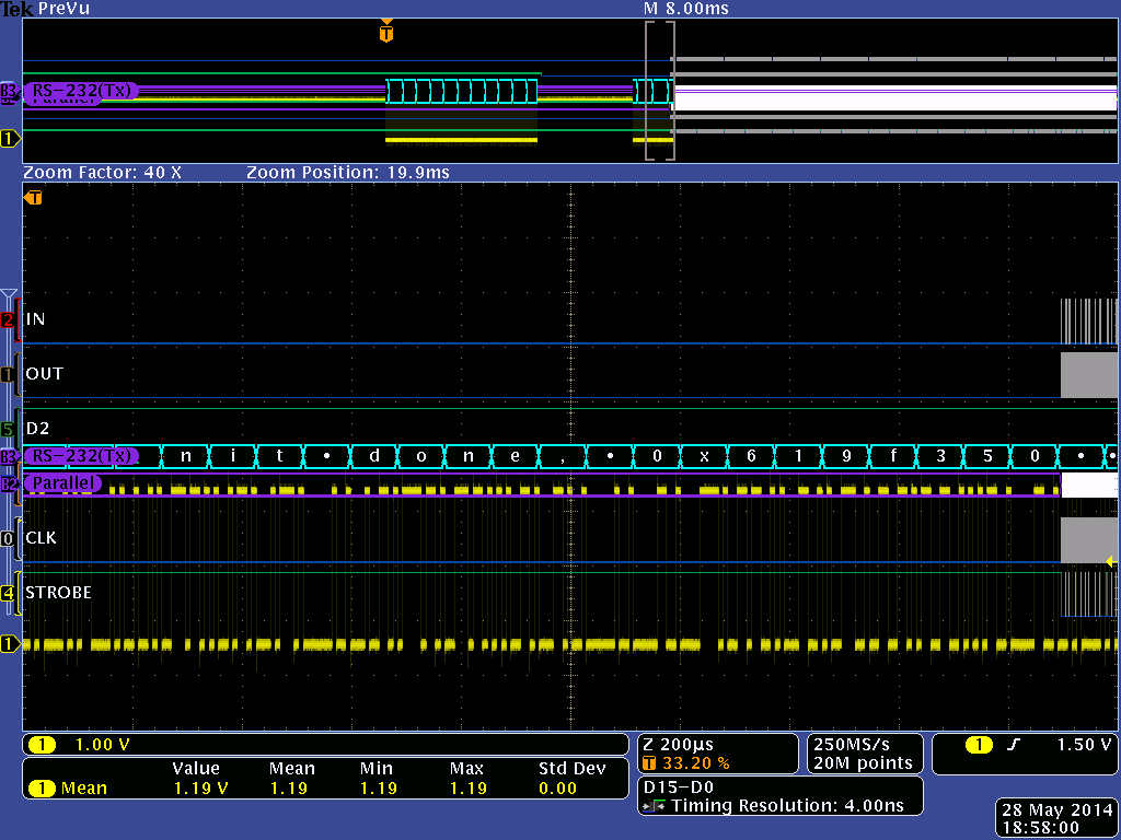

    Above: Screenshot from the Tek MDO4104B-6, showing the analog trace in yellow, and the ASCII data extracted in cyan. The top quarter shows a zoomed-out view of the entire capture; one can clearly see how SPI ROM accesses in gray are punctuated with console output in cyan.

    From here, we needed to speed up our measure-modify-test loop; desoldering the ROM, sticking it in a burner, and resoldering it onto the board was going to get old really fast. Given that we had previously implemented a NAND FLASH ROMulator on Novena, it made sense to re-use that code base and implement a SPI ROMulator. We hacked up a GPBB board and its corresponding FPGA code, and implemented the ability to swap between the original boot SPI ROM and a dual-ported 64kiB emulator region that is also memory-mapped into the Novena Linux host’s address space.
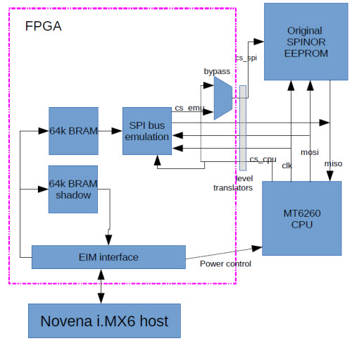

    Block diagram of the SPI ROMulator FPGA
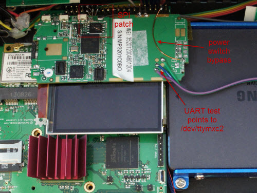

    There’s a phone in my Novena! What’s that doing there?

    A combination of these tools – the address stream determined by the Tek oscilloscope, rapid ROM patching by the ROMulator, and static code analysis using IDA (we found a SHA-1 implementation) – enabled us to determine that the initial bootloader, which we refer to as the 1bl, was hash-checked using a SHA-1 appendix.

    Building a Beachhead

    The next step was to create a small interactive shell which we could use as a beachhead for running experiments on the target hardware. Xobs created a compact REPL environment called Fernly which supports commands like peeking and poking to memory, and dumping CPU registers.

    Because we designed the ROMulator to make the emulated ROM appear as a 64k memory-mapped window on a Linux host, it enables the use a variety of POSIX abstractions, such as mmap(), open() (via /dev/mem), read() and write(), to access the emulated ROM. xobs used these abstractions to create an I/O target for radare2. The I/O target automatically updates the SHA-1 hash every time we made changes in the 1bl code space, enabling us to do cute things like interactively patch and disassemble code within the emulated ROM space.
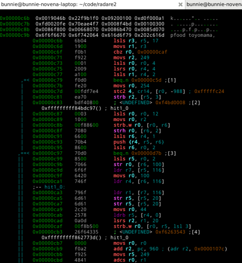
    We also wired up the power switch of the phone to an FPGA I/O, so we could write automated scripts that toggle the power on the phone while updating the ROM contents, allowing us to do automated fuzzing of unknown hardware blocks.

    Attaching a Debugger

    Because of the difficulty in trying to locate critical blocks, and because JTAG is multiplexed with critical functions on the target device, an unconventional approach was taken to attach a debugger: xobs emulates the ARM core, and uses his fernly shell to reflect virtual loads and stores to the live target. This allows us to attach a remote debugger to the emulated core, bypassing the need for JTAG and allowing us to use cross-platform tools such as IDA on x86 for the reversing UI.

    At the heart of this technique is Qemu, a multi-platform system emulator. It supports emulating ARM targets, specifically the ARMv5 used in the target device. A new machine type was created called “fernvale” that implements part of the observed hardware on the target, and simply passes unknown memory accesses directly to the device.

    The Fernly shell was stripped down to only support three commands: write, read, and zero-memory. The write command pokes a byte, word, or dword into RAM on the live target, and a read command reads a byte, word, or dword from the live target. The zero-memory command is an optimization, as the operating system writes large quantities of zeroes across a large memory area.

    In addition, the serial port registers are hooked and emulated, allowing a host system to display serial data as if it were printed on the target device. Finally, SPI, IRAM, and PSRAM are all emulated as they would appear on the real device. Other areas of memory are either trapped and funneled to the actual device, or are left unmapped and are reported as errors by Qemu.


    The diagram above illustrates the architecture of the debugger.

    Invoking the debugger is a multi-stage process. First, the actual MT6260 target is primed with the Fernly shell environment. Then, the Qemu virtual ARM CPU is “booted” using the original vendor image – or rather, primed with a known register state at a convenient point in the boot process. At this point, code execution proceeds on the virtual machine until a load or store is performed to an unknown address. Virtual machine execution is paused while a query is sent to the real MT6260 via the Fernly shell interface, and the load or store is executed on the real machine. The results of this load or store is then relayed to the virtual machine and execution is resumed. Of course, Fernly will crash if a store happens to land somewhere inside its memory footprint. Thus, we had to hide the Fernly shell code in a region of IRAM that’s trapped and emulated, so loads and stores don’t overwrite the shell code. Running Fernly directly out of the SPI ROM also doesn’t work as part of the initialization routine of the vendor binary modifies SPI ROM timings, causing SPI emulation to fail.

    Emulating the target CPU allows us to attach a remote debugger (such as IDA) via GDB over TCP without needing to bother with JTAG. The debugger has complete control over the emulated CPU, and can access its emulated RAM. Furthermore, due to the architecture of qemu, if the debugger attempts to access any memory-mapped IO that is redirected to the real target, the debugger will be able to display live values in memory. In this way, the real target hardware is mostly idle, and is left running in the Fernly shell, while the virtual CPU performs all the work. The tight integration of this package with IDA-over-GDB also allows us to very quickly and dynamically execute subroutines and functions to confirm their purpose.

    Below is an example of the output of the hybrid Qemu/live-target debug harness. You can see the trapped serial writes appearing on the console, plus a log of the writes and reads executed by the emulated ARM CPU, as they are relayed to the live target running the reduced Fernly shell.

    bunnie@bunnie-novena-laptop:~/code/fernvale-qemu$ ./run.sh 
    
    ~~~ Welcome to MTK Bootloader V005 (since 2005) ~~~
    **===================================================**
    
    READ WORD Fernvale Live 0xa0010328 = 0x0000... ok
    WRITE WORD Fernvale Live 0xa0010328 = 0x0800... ok
    READ WORD Fernvale Live 0xa0010230 = 0x0001... ok
    WRITE WORD Fernvale Live 0xa0010230 = 0x0001... ok
    READ DWORD Fernvale Live 0xa0020c80 = 0x11111011... ok
    WRITE DWORD Fernvale Live 0xa0020c80 = 0x11111011... ok
    READ DWORD Fernvale Live 0xa0020c90 = 0x11111111... ok
    WRITE DWORD Fernvale Live 0xa0020c90 = 0x11111111... ok
    READ WORD Fernvale Live 0xa0020b10 = 0x3f34... ok
    WRITE WORD Fernvale Live 0xa0020b10 = 0x3f34... ok
    

    From this beachhead, we were able to discover the offsets of a few IP blocks that were re-used from previous known Mediatek chips (such as the MT6235 in the osmocomBB http://bb.osmocom.org/trac/wiki/MT6235) by searching for their “signature”. The signature ranged from things as simple as the power-on default register values, to changes in bit patterns due to the side effects of bit set/clear registers located at offsets within the IP block’s address space. Using this technique, we were able to find the register offsets of several peripherals.
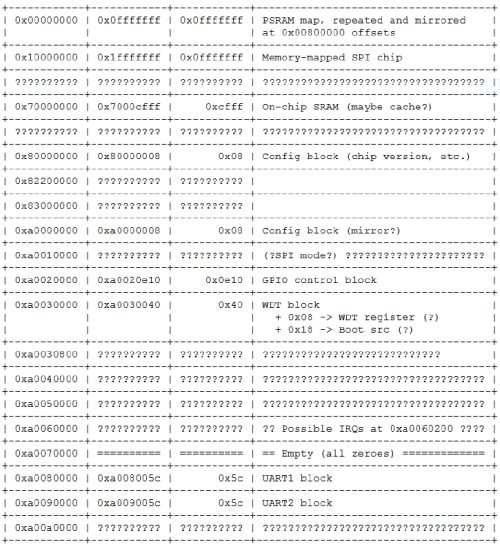
    Booting an OS

    From here we were able to progress rapidly on many fronts, but our goal of a port of NuttX remained elusive because there was no documentation on the interrupt controller within the canon of Shanzhai datasheets. Although we were able to find the routines that installed the interrupt handlers through static analysis of the binaries, we were unable to determine the address offsets of the interrupt controller itself.

    At this point, we had to open the Mediatek codebase and refer to the include file that contained the register offsets and bit definitions of the interrupt controller. We believe this is acceptable because facts are not copyrightable. Justice O’Connor wrote in Feist v. Rural (449 U.S. 340, 345, 349 (1991). See also Sony Computer Entm’t v. Connectix Corp., 203 F. 3d 596, 606 (9th Cir. 2000); Sega Enterprises Ltd. v. Accolade, Inc., 977 F.2d 1510, 1522-23 (9th Cir. 1992)) that
    “Common sense tells us that 100 uncopyrightable facts do not magically change their status when gathered together in one place. … The key to resolving the tension lies in understanding why facts are not copyrightable: The sine qua non of copyright is originality”

    and

    “Notwithstanding a valid copyright, a subsequent compiler remains free to use the facts contained in another’s publication to aid in preparing a competing work, so long as the competing work does not feature the same selection and arrangement”.

    And so here, we must tread carefully: we must extract facts, and express them in our own selection and arrangement. Just as the facts that “John Doe’s phone number is 555-1212” and “John Doe’s address is 10 Main St.” is not copyrightable, we need to extract facts such as “The interrupt controller’s base address in 0xA0060000”, and “Bit 1 controls status reporting of the LCD” from the include files, and re-express them in our own header files.

    The situation is further complicated by blocks for which we have absolutely no documentation, not even an explanation of what the registers mean or how the blocks function. For these blocks, we reduce their initialization into a list of address and data pairs, and express this in a custom scripting language called “scriptic”. We invented our own language to avoid subconscious plagiarism – it is too easy to read one piece of code and, from memory, code something almost exactly the same. By transforming the code into a new language, we’re forced to consider the facts presented and express them in an original arrangement.

    Scriptic is basically a set of assembler macros, and the syntax is very simple. Here is an example of a scriptic script:
    #include "scriptic.h"
    #include "fernvale-pll.h"
    
    sc_new "set_plls", 1, 0, 0
    
      sc_write16 0, 0, PLL_CTRL_CON2
      sc_write16 0, 0, PLL_CTRL_CON3
      sc_write16 0, 0, PLL_CTRL_CON0
      sc_usleep 1
    
      sc_write16 1, 1, PLL_CTRL_UPLL_CON0
      sc_write16 0x1840, 0, PLL_CTRL_EPLL_CON0
      sc_write16 0x100, 0x100, PLL_CTRL_EPLL_CON1
      sc_write16 1, 0, PLL_CTRL_MDDS_CON0
      sc_write16 1, 1, PLL_CTRL_MPLL_CON0
      sc_usleep 1
    
      sc_write16 1, 0, PLL_CTRL_EDDS_CON0
      sc_write16 1, 1, PLL_CTRL_EPLL_CON0
      sc_usleep 1
    
      sc_write16 0x4000, 0x4000, PLL_CTRL_CLK_CONDB
      sc_usleep 1
    
      sc_write32 0x8048, 0, PLL_CTRL_CLK_CONDC
      /* Run the SPI clock at 104 MHz */
      sc_write32 0xd002, 0, PLL_CTRL_CLK_CONDH
      sc_write32 0xb6a0, 0, PLL_CTRL_CLK_CONDC
      sc_end
    

    This script initializes the PLL on the MT6260. To contrast, here’s the first few lines of the code snippet from which this was derived:

    // enable HW mode TOPSM control and clock CG of PLL control 
    
    *PLL_PLL_CON2 = 0x0000; // 0xA0170048, bit 12, 10 and 8 set to 0 to enable TOPSM control 
                            // bit 4, 2 and 0 set to 0 to enable clock CG of PLL control
    *PLL_PLL_CON3 = 0x0000; // 0xA017004C, bit 12 set to 0 to enable TOPSM control
    
    // enable delay control 
    *PLL_PLLTD_CON0= 0x0000; //0x A0170700, bit 0 set to 0 to enable delay control
    
    //wait for 3us for TOPSM and delay (HW) control signal stable
    for(i = 0 ; i < loop_1us*3 ; i++);
    
    //enable and reset UPLL
    reg_val = *PLL_UPLL_CON0;
    reg_val |= 0x0001;
    *PLL_UPLL_CON0  = reg_val; // 0xA0170140, bit 0 set to 1 to enable UPLL and generate reset of UPLL
    

    The original code actually goes on for pages and pages, and even this snippet is surrounded by conditional statements which we culled as they were not relevant facts to initializing the PLL correctly.

    With this tool added to our armory, we were finally able to code sufficient functionality to boot NuttX on our own Fernvale hardware.
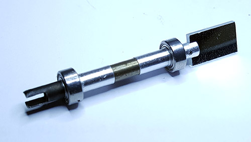
    Toolchain

    Requiring users to own a Novena ROMulator to hack on Fernvale isn't a scalable solution, and thus in order to round out the story, we had to create a complete developer toolchain. Fortunately, the compiler is fairly cut-and-dry – there are many compilers that support ARM as a target, including clang and gcc. However, flashing tools for the MT6260 are much more tricky, as all the existing ones that we know of are proprietary Windows programs, and Osmocom's loader doesn't support the protocol version required by the MT6260. Thus, we had to reverse engineer the Mediatek flashing protocol and write our own open-source tool.
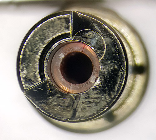
    Fortunately, a blank, unfused MT6260 shows up as /dev/ttyUSB0 when you plug it into a Linux host – in other words, it shows up as an emulated serial device over USB. This at least takes care of the lower-level details of sending and receiving bytes to the device, leaving us with the task of reverse engineering the protocol layer. xobs located the internal boot ROM of the MT6260 and performed static code analysis, which provided a lot of insight into the protocol. He also did some static analysis on Mediatek's Flashing tool and captured live traces using a USB protocol analyzer to clarify the remaining details. Below is a summary of the commands he extracted, as used in our open version of the USB flashing tool.

    enum mtk_commands {
      mtk_cmd_old_write16 = 0xa1,
      mtk_cmd_old_read16 = 0xa2,
      mtk_checksum16 = 0xa4,
      mtk_remap_before_jump_to_da = 0xa7,
      mtk_jump_to_da = 0xa8,
      mtk_send_da = 0xad,
      mtk_jump_to_maui = 0xb7,
      mtk_get_version = 0xb8,
      mtk_close_usb_and_reset = 0xb9,
      mtk_cmd_new_read16 = 0xd0,
      mtk_cmd_new_read32 = 0xd1,
      mtk_cmd_new_write16 = 0xd2,
      mtk_cmd_new_write32 = 0xd4,
      // mtk_jump_to_da = 0xd5,
      mtk_jump_to_bl = 0xd6,
      mtk_get_sec_conf = 0xd8,
      mtk_send_cert = 0xe0,
      mtk_get_me = 0xe1, /* Responds with 22 bytes */
      mtk_send_auth = 0xe2,
      mtk_sla_flow = 0xe3,
      mtk_send_root_cert = 0xe5,
      mtk_do_security = 0xfe,
      mtk_firmware_version = 0xff,
    };
    

    Current Status and Summary

    After about a year of on-and-off effort between work on the Novena and Chibitronics campaigns, we were able to boot a port of NuttX on the MT6260. A minimal set of hardware peripherals are currently supported; it’s enough for us to roughly reproduce the functionality of an AVR used in an Arduino-like context, but not much more. We’ve presented our results this year at 31C3 (slides).

    The story takes an unexpected twist right around the time we were writing our CFP proposal for 31C3. The week before submission, we became aware that Mediatek released the LinkIT ONE, based on the MT2502A, in conjunction with Seeed Studios. The LinkIT ONE is directly aimed at providing an Internet of Things platform to entrepreneurs and individuals. It’s integrated into the Arduino framework, featuring an open API that enables the full functionality of the chip, including GSM functions. However, the core OS that boots on the MT2502A in the LinkIT ONE is still the proprietary Nucleus OS and one cannot gain direct access to the hardware; they must go through the API calls provided by the Arduino shim.

    Realistically, it’s going to be a while before we can port a reasonable fraction of the MT6260’s features into the open source domain, and it’s quite possible we will never be able to do a blob-free implementation of the GSM call functions, as those are controlled by a DSP unit that’s even more obscure and undocumented. Thus, given the robust functionality of the LinkIT ONE compared to Fernvale, we’ve decided to leave it as an open question to the open source community as to whether or not there is value in continuing the effort to reverse engineer the MT6260: How important is it, in practice, to have a blob-free firmware?

    Regardless of the answer, we released Fernvale because we think it’s imperative to exercise our fair use rights to reverse engineer and create interoperable, open source solutions. Rights tend to atrophy and get squeezed out by competing interests if they are not vigorously exercised; for decades engineers have sat on the sidelines and seen ever more expansive patent and copyright laws shrink their latitude to learn freely and to innovate. I am saddened that the formative tinkering I did as a child is no longer a legal option for the next generation of engineers. The rise of the Shanzhai and their amazing capabilities is a wake-up call. I see it as evidence that a permissive IP environment spurs innovation, especially at the grass-roots level. If more engineers become aware of their fair use rights, and exercise them vigorously and deliberately, perhaps this can catalyze a larger and much-needed reform of the patent and copyright system.

    Want to read more? Check out xobs’ post on Fernvale. Want to get involved? Chime in at our forums. Or, watch the recording of our talk below.

    Team Kosagi would like to once again extend a special thanks to .mudge for making this research possible.