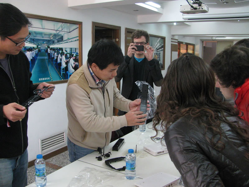
This month, I will be teaching a few MIT Media Lab graduate students and doing a bit of a “geek tour” of Shenzhen – we will visit several factories and live among the electronic markets to facilitate new directions and expand horizons in the students’ hardware-oriented research projects.
As part of the course, they will learn how to scale up their research utilizing the China manufacturing ecosystem. These lessons may also be useful for Makers looking to bootstrap a product in moderate volumes (hundreds to thousands of units). I will share some tips and insights from the course in four posts over the next month covering:
- Getting a quotation: documentation standards (how to make a BOM)
- Process optimization: design for manufacturing and test jigs
- Industrial design for startups: guerrilla engineering on a shoestring budget
- How to pick a factory: building and maintaining partnerships
Part 1 of 4: The Quotation (or, How to Make a BOM)
Most Makers trying to scale up quickly realize the only practical path forward is to outsource production. If only outsourcing were as easy as schematic + cash = product! Whether working with the assembly shop down the street or going to China, a clear and complete bill of materials (BOM) is the first step to outsourcing production.
Every single assumption, down to the color of the soldermask, has to be spelled out unambiguously for a third party to faithfully reproduce a design. Missing or incomplete documentation is the lead cause of production delays, defects, and cost overruns. So, we will start the series on the topic of making a complete and accurate BOM for quotation.
Let’s consider a simple case study. Suppose we Kickstarted a bicycle safety light. It contains a circuit using the 555 timer to flash a small array of LEDs. After a great marketing campaign, we now have to fill several hundred orders in a few months’ time.
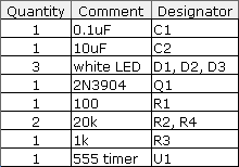
At this point, here’s how the starting BOM might look:

This BOM, along with a schematic, is likely sufficient for an engineer to reproduce the prototype, but this is far from adequate for a manufacturing cost quotation. Here’s some of the things missing from the BOM:
- Approved manufacturer for each component
- Tolerance, material composition, and voltage spec for passive components
- Package type information for all parts
- Extended part numbers specific to each manufacturer
Furthermore, the table above addresses only the electronics BOM. A complete BOM for an LED flasher also needs to include the PCB, battery, plastic case pieces, lens, screws, any labeling (for example, a serial number), a manual, and packaging (plastic bag plus cardboard box, for example). There may also need to be a master carton as a single boxed LED flasher is too small to ship on its own. Although cardboard boxes are cheap, they aren’t free, and if they aren’t ordered on time, inventory will sit on the dock until a master carton is delivered for final pack-out prior to shipment.
Here’s a little more about each of the missing items from the example BOM.
Approved manufacturers
A proper factory will require the allowed manufacture(s) to be specified for every part. This is frequently referred to as the “AVL”, or Approved Vendor List. A manufacturer is not a distributor (i.e., Digikey, Mouser, Avnet); a manufacturer is the actual company that makes the part. A capacitor, for example, could be made by TDK, Murata, Taiyo Yuden, AVX, Panasonic, Samsung, etc. You’ll be surprised how many times I’ve reviewed a BOM listing “Digikey” or some other distributor as the manufacturer for a part.
While it may seem silly to trifle over who makes a capacitor, there are definitely situations in which the maker of a component matters – even for the humble capacitor. For example, blindly substituting the filter capacitors on a switching regulator, even if the substitute has the same rated capacitance and voltage, can lead to unstable operation and even boards catching fire.
Of course, there are times when one is truly insensitive to the manufacturer, in which case I would mark on the BOM “any/open” for the AVL (particularly true for things like pull-up resistors). This invites the factory to suggest their preferred supplier on your behalf.
Tolerance, composition, and voltage spec
For passive components that are marked as “any/open”, there are some key parameters that should always be specified in a BOM to ensure the right part is purchased:
- For resistors, at a minimum the tolerance and wattage should be specified. A 1k, 1% 1/4W carbon resistor is very different beast from a 1k, 5% 1W wirewound resistor!
- For capacitors, at a minimum the tolerance, voltage rating, and dielectric type should be specified. For special applications, certain parameters such as ESR or ripple current tolerance also need to be specified. A 10uF, electrolytic, 10% 50V capacitor has vastly different performance at high frequencies compared to a 10uF, X7R [ceramic], 20% 16V capacitor.
- Inductors are sufficiently specialized that it’s not recommended to ever leave them as “any/open”. For power inductors, core composition, DCR, saturation, temperature rise current, are the basic parameters, but there is also no standard for casing like there is for resistors and capacitors. Furthermore, important parameters such as shielding and potting, which can have material impacts on the performance of a circuit, are often implicit in a part number; hence, it’s best to simply fully specify the inductor and not leave it any/open. The same goes for RF inductors.
Electronic component form factor
It’s always important to fully specify the form factor, or “package type”, of a component. Poorly specified or under-specified package parameters can lead to assembly errors. Beyond the basic parameters such as the EIA or JEDEC package code (0402, 0805, TSSOP, etc.), here are some other things to consider:
- For SMT packages, the height of a component can vary, particularly for packages larger than 1206, or inductors. Pay attention if the board is slotting into a tight case.
- For through-hole packages, lead pitch and component height should always be specified.
- For ICs, try to specify the common name that corresponds to the package, not just the manufacturer’s internal code (for example, a TI “DW” type package code corresponds to SOIC). It’s a good consistency check that can guard against errors.
Extended part numbers
Designers often think using abbreviated part numbers. A great example of this is the 7404. The venerable 7404 is a hex inverter, and has been in service for decades. Because of its ubiquity, the term “7404” can be used as a generic term for an inverter. However, when going to production, things like the package type, manufacturer and logic family must be specified. A complete part number might be 74VHCT04AMTC, which specifies an inverter made by Fairchild Semiconductor, from the “VHCT” series, in a TSSOP package, shipped in tubes. The extra characters are very important, because small variations can lead to big problems, such as quoting and ordering the wrong packaged device (and subsequently being stuck with a reel of unusable parts), or subtle reliability problems. In fact, I encountered a problem once due to a mistaken substitution of a “VHC” for the “VHCT” logic family part. This switched the input thresholds of the inverter from TTL to CMOS logic-compatible, and resulted in some units having an asymmetric response to input signals. Fortunately, I caught this problem before production ramped, avoiding a whole lot of potential rework or worse yet, returns.
Here’s another example of how missing a couple of characters can cost thousands of dollars. A fully specified part number for the LM3670 switching regulator might be LM3670MFX-3.3/NOPB. Significantly, if the /NOPB is omitted, the part number is still valid and orderable – but for a version that uses leaded solder. This could be disastrous for products exporting to a region, such as the EU, that requires RoHS compliance (meaning lead-free, among other things). A more subtle issue is the “X” in the part number. Part numbers with an “X” come with 3,000 pieces to a reel, and ones lacking an “X” come in 1,000 pieces to a reel. While many factories will question the /NOPB omission (since factories typically assemble RoHS documentation as they purchase parts), they will rarely flag the reel quantity as an issue. However, you care about the reel quantity because if you only wanted 1,000 pieces, including the X in the part number means you’ll be paying for 2,000 extra pieces you don’t need. Or, if you’re doing a much larger production run and you omit the X, you could be paying a premium for shipping three times the volume of reels for the same purchase quantity. Either way, the factory will quote the part exactly as specified, and you could be missing out on a cost savings if you’re not paying attention to the reel quantities.
The bottom line is that every digit and character counts, and lack of attention to detail can cost real money!
BOM Revisited
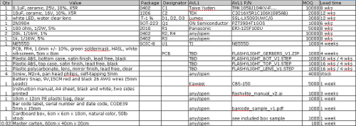
Here’s an example of how a proper, fully-specified BOM for quotation of the same project example above would look.

(click for a larger version, or get the original in open office format here)
Note that the BOM above doesn’t call out factory margin, labor for assembly, pack-out, shipping, duties, etc. These “soft costs” will be discussed in the final post of the series. However, it’s important to note that when building a business model, parts cost is not the only cost to consider — the above BOM just gets you started with the initial quotation process.
Let’s compare this to our original BOM for contrast:

There is big difference between a BOM that any engineer could take to produce a prototype, and a BOM that any factory could take to mass-produce a product.
Note that two additional columns have crept into the final BOM, the “MOQ” (minimum order quantity) and the “lead time”. These columns are irrelevant when building low-volume prototypes, as one would typically buy parts from distributors which have few MOQ restrictions and maintain stock on hand for next-day deliveries. However, when scaling into production, a big cost savings are realized by cutting the distributor overhead and buying through wholesale channels. In wholesale channels, MOQs and lead times matter.
The good news is the factory will fill in the MOQ and lead time as part of the quotation process. However, these are parameters that are helpful to be tracked from the beginning of a design. If the MOQ of a particular component is very high, one may have to buy massive numbers of excess parts which increases the effective price of the project. If the lead time of a part is very long, one may want to consider redesigning for a part with a shorter lead time. Using parts with shorter lead times not only saves time, it improves cash flow, as the last thing anyone wants to do is tie up cash on long-lead components 4 months in advance of any sales revenue.
Also note the inclusion of all the “miscellaneous” bits for the design inside the BOM, left out on the engineering prototype’s BOM. The miscellaneous bits are easy to forget, but a missing user manual in an initial BOM is often times not discovered until opening the final sample for approval, leading to a last-minute scramble to get it into the final product. Many, many products have been delayed or late simply because a user manual or box art was not completed and approved in time, and it sucks to have a hundred thousand dollars worth of inventory idling in a warehouse for want of a slip of paper.
Finally, it’s best practice to provide the factory with “golden samples” along with CAD files. These prototypes enable the factory to make smarter decisions about any ambiguities in the submitted BOM. It may suck to hand-solder together one more unit just for the factory, but in my opinion a few hours of soldering beats a week of trading clarifying emails with the factory.
Coping with Change
Designs change. Even if a design is perfect, sometimes vendors End-of-Life (EOL) components, forcing a change to the design. And let’s face it, not all design assumptions survive contact with real consumers. While the quotation process is fluid, it’s important to formalize the change process once crossing the threshold into production. It is best practice to use a written, formal Engineering Change Orders (ECO) to update the factory on any changes after the initial quotation is completed. An ECO template should have at a minimum the documentation detailing each part changed and brief explanation of why, along with a unique revision number for conveniently referencing the change down the road, and a method to record the factory’s receipt of the ECO paperwork. Failing to be thorough about ECOs and relying on casual emails will often lead to buyers buying the wrong part, or worse yet the factory installing the wrong part and entire lots being scrapped or reworked. Even after troubleshooting a problem with the factory engineers, I will still write up a formal ECO and submit it to the production staff to formalize the findings. I hate paperwork as much as the next engineer, but in production one small mistake can cost tens of thousands of dollars, and that thought keeps me disciplined on ECOs.
Stay tuned for next week when I cover design for manufacturing and test jigs.


