It’s the year 2009, and I’m wondering: where is my flying car? After all, Hollywood reels from the 60’s and 70’s all predicted that flying cars are what I’d be using to get around town these days. Of course, automotive technology isn’t the only victim of Hollywood hype. The potential impact of personalized genomics has been greatly overstated in movies like GATTACA. This has lead to the pervasive myth that your genome is like a crystal ball, and somehow your fate is predestined by your genetic programming. Recently, my perlfriend co-authored a paper in Nature (“A Personalized Medicine Research Agenda”, Nature Vol 461, October 8 2009), comparing Navigenics’ and 23andMe’s “Direct to Consumer” (DTC) personal genomics offerings. She’s qualified to offer deep insight into personal genomics, since she designed the original Illumina bead chip used by leading companies to generate their DTC genetic data, and she is also the person who made sense of the first complete diploid human genome sequence (1 2). She’s sort of the biology equivalent of the reverse engineer who takes binary sequences and annotates meaning into the disassembled binary sequences. So, let the mythbusting begin.
Myth: having your genome read is like hex-dumping the ROM of your computer. Many people (I was one of them) have the impression that “reading your genome” means that at the end of the day someone has a record of all the base pairs of DNA in my genome. This is called a “full sequence”. In reality, full sequencing is still cost-prohibitive, and instead a technique called “genotyping” is used. Here, a selective diff is done between your genome and a “reference” human genome, or in other words, your genome is simply sampled in potentially interesting spots for single-point mutations called Single Nucleotide Polymorphisms (SNPs, pronounced “snips”). In the end, about 1 in 3000 base pairs are actually sampled in this process. Thus, the result of a personalized genomic screen is not your entire sequence, but a subset of potentially interesting mutations compared against a reference genome. This naturally leads to two questions: first, how do you choose the “interesting subset” of SNPs to sample? And second, how do we know the reference genome is an accurate comparison point? This sets us up to bust another two myths.
Myth: We know which mutations predict disease. Herein lies a subtle point. Many of the mutations are simply correlative with disease, but not proven to be predictive or causal with disease. The truth is that we really don’t understand why many genetic diseases happen. For poorly understood diseases (which is still most of them), all we can say is that people who have a particular disease tend to have a certain pattern of SNP mutations. It’s important not to confuse causality with correlation. Doing so might lead you to conclude, for example, that diet coke makes you fat, because diet coke is often consumed by people who are overweight.
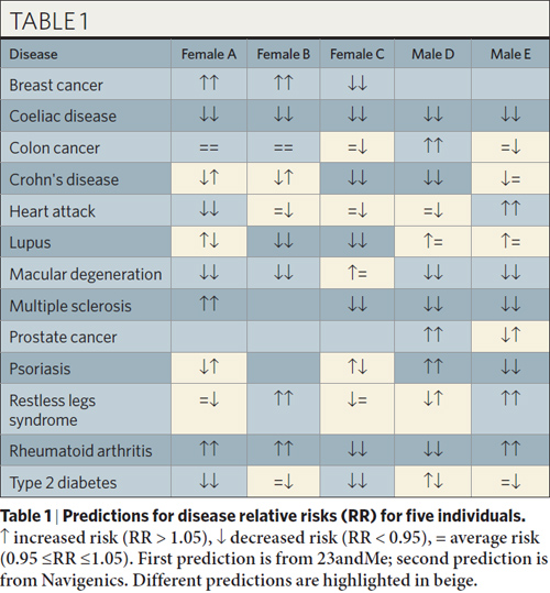
Thus, there are two echelons of understanding that can come from a genotype: disease correlations, and disease causes. The majority of SNP mutation-based “predictions” are correlative, not causative. As a result, a genotype should not be considered a “crystal ball” for predicting your disease future; rather, it is closer to a “Rorschach blot” that we have to squint and stare at for a while before we can make a statement about what it means. The table below from the paper illustrates how varied disease predictions can be as a result of these disagreements on the interpretation of mutation meanings.
Myth: the “reference genome” is accurate reference. The term “reference genome” alone should tip you off on a problem: it implies there is such a thing as “reference people”. Ultimately, just a handful of individuals were sequenced to create today’s reference genome, and most of them are of European ancestry. As time goes on and more full sequence genetic data is collected, the reference genome wlll be merged and massaged to present a more accurate picture of the overall human race, but for now it’s important to remember that a genotype study is a diff against a source repository of questionable universal validity, partially because it’s questionable if there is such a thing as a “reference human”, i.e. there are structural variations and some SNPs have different frequencies in different populations (e.g. the base “A” could dominate in a European population, but at that same position, the base “G” could dominate in an African population). It’s also important to keep in mind that the “reference genome” has an aggregate error rate of about 1 error every 10,000 base pairs, although to be fair the process of discovering a disease variant usually cleans up any errors in the reference genome for the relevant sequence regions.
So now you can see that in fact “reading your genome” is less of looking into a crystal ball and more of staring at a Rorschach blot obscured by cheesecloth (i.e., the genome is simply sampled and not sequenced). And, even if we could remove the cheesecloth and sequence the genome such that we knew every base pair, it would still be … a Rorschach blot, but in high resolution. It will be decades until we have a full understanding of what all the sequences mean, and even then it’s unclear if they are truly predictive.
Here lies perhaps the most important message, and a point I cannot make fine enough: in most situations, environment has as much, perhaps even more, to do with whom you are, what you become, and what diseases you may develop than your genes. If there is any upside to personal genomics, it won’t be due to crystal ball predictions. It will be the lifestyle changes it can encourage. If there’s one thing I’ve learned from dating a preeminent bioinformaticist, it’s that no matter your genetic makeup, most common diseases can be prevented with proper diet and exercise.