The Youscope demo is a hard act to follow up on, but I’ve had this scope screenshot for a while now and I thought it was so neat that I wanted to talk about it a bit on the blog.

Before I dive into the post, let me say that the best accessory I ever bought for my scope (a Tek TDS5104B–don’t let anyone ever tell you an Agilent is better than a Tek!) is the P6245 active probe. After suffering for many years with a Kikusui 100 MHz analog scope with second-hand passive probes, the quality of measurements I get with the active probe and the TDS5104B brings a tear to my eye. For the first time ever I can see traces that actually look like the darn SPICE simulations.
Here’s the background behind what we’re looking at in the screenshot. The top trace is the data line of a memory bus; the bottom line is the clock. The trigger is set on the data line–not the clock line as you’d expect. The test pattern being run is a repeated 0xFFFFFFFF-0x00000000 transition using four different bus drive strengths in sequence on the microprocessor. You can see each of the four drive strengths on the bottom clock trace, for example, at point “C”.
The particular bug this trace is supposed to capture is a ground bounce problem, as shown at point “B”. The rising transition “F” is what causes the ground bounce at “B” (note that the dip at “B” does not happen on anywhere else). The reason “F” trails the ground bounce event is because the cable of the passive probe used for the Data line has a fairly long delay–another measurement was used to calibrate out this fixed delay. The time difference of F – A approximates the delay differential between the active and the passive probes. You can also clearly see the rise time contrast between the two probes in this screen shot.
I think it is so cool that one can so clearly capture a problem as difficult to characterize as on-chip ground bounce using only conventional probes on external signals.
The other really neat thing about this set of scope traces is that it shows the timing of both the microprocessor->memory and the memory->microprocessor in a single shot. This is because I’m triggering off of the data line, not the clock line. On the data trace, you can clearly see the Processor-driven data trajectory (“D”) and the Memory-driven data trajectory (“E”). On the clock trace, you can see two phase-shifted versions of the clock. One of them is the clock timing relative to when the CPU drives the bus–this is G-F. The other one is the clock timing relative to when the Memory drives the bus–this is C-F (minus a clock period). So in a single picture, you can divine the available setup/hold margin in both directions of the bus!
You can also see other “good things” in the scope trace, such as the auxiliary measurements for frequency, amplitude, duty cycle, and rise time. You can also see how the clock trace is pretty well formed overall, with minimal over/undershoot, and you can get an idea of how much a passive scope probe introduces overshoot artifacts by contrasting it against the top trace. This picture is truly worthy of a thousand words!
OK, so I’m a real geek for getting so excited about a screen shot like this, but really, after teaching this sort of stuff for several years at MIT and then running countless simulations of chips to validate scenarios like this, it’s somehow very satisfying to be able to go into lab and actually see that the real world does match up with theory so nicely (even if it is a bug). If I ever teach digital design again, this shot is going into my slides and my problem sets.
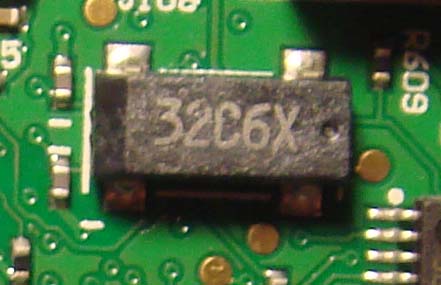
And, yes, this was a problem found on the chumby DVT prototypes some months ago and it has since been resolved. This ground bounce, under certain conditions, would upset the internal clock multiplier of the CPU. The fix involved multiple improvements to the board layout, but in the end nothing can compensate for the relatively high inductance designed into the chip package. Therefore, the most important fix was to use a much higher clock frequency reference so the multiplication factor was only on the order of 20x instead of 10,000x (a 16 MHz reference instead of a 32.768 kHz reference). Reducing the period of ground-bounce noise integration by a factor of 500 resolved the stability problems of the internal VCO of the CPU’s clock multiplier PLL.
