Winner, Name that Ware December 2012

January 29th, 2013

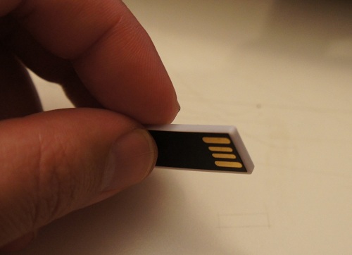
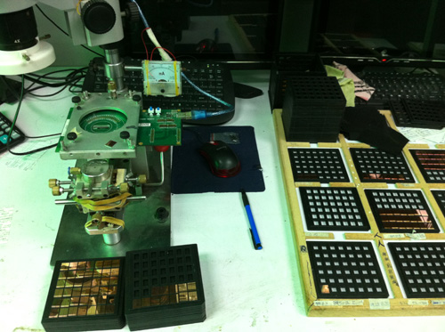
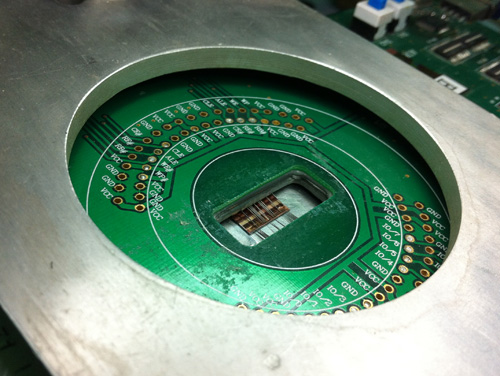
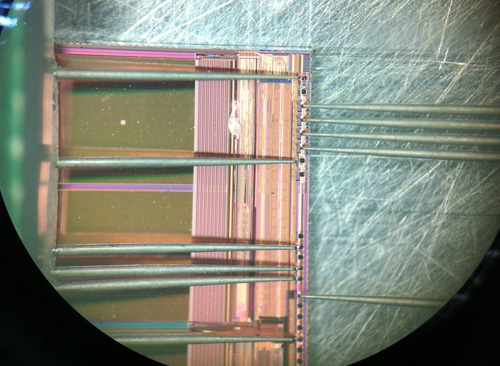
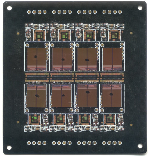
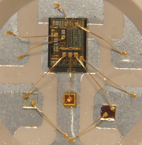
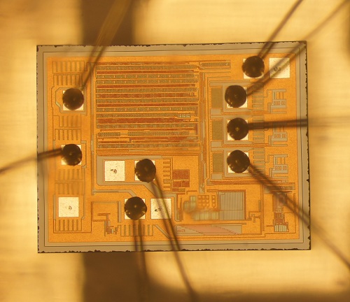
The Ware for December 2012 are boards from a 2100MHz RF PA module with digital predistortion, from a defunct company named Wiseband.

The submitter of the ware notes that there is a patent that is a close hit on this design, see figure 4 of “Super-linear multi-carrier power amplifier“. The PA board is block 108, the digital board is block 124; the rf board, with the 3 downconverters and 1 upconverter, is block 120, with some components connected externally to the board (not seen in the scans) – the delay lines and the error amplifier (154, 156).

Picking a winner this time is like throwing darts — lots of insightful analysis, but no exact matches. I’ll go with…Andy Bardagjy, email me for your prize!

A Moment of Silence for Aaron Swartz

January 19th, 2013

I am joining three academic research web sites, SIFT and Polyphen (websites for predicting disease mutations) and CRAVAT (a website for predicting cancer mutations), in a moment of silence to mark Aaron Swartz’ passing. On January 25, we will bring down our sites for the day to honor his contributions and mark the tragedy of his passing.

Aaron’s treatment by MIT is not unfamiliar to me. Back when I was a graduate student there, I extracted security keys from the original Microsoft Xbox video game console. I still remember the crushing disappointment of receiving a letter from MIT legal repudiating any association with my work, effectively leaving me on my own to face Microsoft. However, in my case, the faculty of my then-lab, the AI lab, were outraged by this treatment. They openly defied MIT legal by publishing my work as an official AI Lab Memo, thereby granting me greater negotiating leverage with Microsoft. Microsoft, mindful of the potential backlash from the court of public opinion over suing an openly legitimized academic researcher, came to a civil understanding with me over the issue.

It saddens me that America’s so-called government for the people, by the people, and of the people has less compassion and enlightenment toward their fellow man than a corporation. Having been a party myself to subsequent legal bullying by other entities, I am all too familiar with how ugly and gut-wrenching a high-stakes lawsuit can be. Fortunately, the stakes in my cases were not as high, nor my adversaries as formidable as Aaron’s, otherwise I too might have succumbed to hopelessness and fear. A few years ago, I started rebuilding my life overseas, and I find a quantum of solace in the thought that my residence abroad makes it a little more difficult to be served.

While the US legal system strives for justice, the rules of the system create an asymmetric war that favors those with resources. By and far one of the most effective methods to force a conclusion, right or wrong, against a small player is to simply bleed them of resources and the will to fight through pre-trial antics. Your entire life feels like it is under an electron microscope, every tiny blemish magnified into a pitched battle of motions, counter-motions, discovery, subpoenas and affidavits, with each action heaping tens of thousands of dollars onto your legal bill. Your friends, co-workers, employers, and family are drawn into this circus of humiliation as witnesses. Worse yet, you are counseled not to speak your candid thoughts to anyone, lest they be summoned as a witness against you. Isolated and afraid, it eventually makes more sense to roll over and settle than to take the risk of losing on a technicality versus a better-funded adversary, regardless of the justice.

The US government is by and far the most well-funded and fearsome enemy to spar with, and copyright law has some unusually large, if not cruel, penalties associated with it. I don’t know Aaron personally, but I feel the magnitude of the bullying he was subjected to is reflected by his decision to end his life. I echo Larry Lessig’s notion that the legal system in the US needs a sense of shame. At least to an outsider like me, it seems like some prosecutors in the US government are obsessed with making a big name for themselves. Winning cases gets them the recognition and credibility needed for promotions and assignments to ever higher profile cases. It’s not about justice, it’s about victory.

This system of incentives, I feel, contributes to the shameless bullying of individuals and small entities with enough guts to stand up and to do something a little daring. Individuals are robbed of the will and strength to fight for what they feel is right, as the mere act of prosecution can be as much a punishment as the verdict. As a result, I fear the era of civil disobedience may be coming to a close.

What has America become?

The Factory Floor, Part 3 of 4:
Industrial Design for Startups

January 19th, 2013

The geek tour continues on. Akiba has new posts up covering our visit to a motor factory, Huawei, CTS, and also a side trip to get full custom clothes and bags tailor made. The photos from the motor factory and the custom tailoring expedition came out particularly well.

And now, on to part 3 of 4 of “The Factory Floor” series…

Industrial Design for Startups:
Guerrilla Engineering on a Shoestring Budget

Sex sells. The performance of a CPU or amount of RAM in a box, to within a factor of two or so, is less important to a typical consumer than how the device looks. Apple devices command a hefty premium in part because of their slick industrial design, and many product designers aim to emulate the success of Sir Jony Ives in their own products.

There are many schools of thought in industrial design. One school invokes the monastic designer, coming up with a beautiful, pure concept, and the only thing the production engineers can do is spoil the purity of the design. Another school invokes the pragmatist designer, working closely with the production engineers, hammering out gritty compromises to produce an inexpensive and high-yielding design.

In my experience, neither extreme is compelling. The monastic approach often results in an unmanufacturable product that is either late to market or exorbitant to produce. The pragmatist approach often results in in a cheap look and feel, to which consumers have trouble assigning a significant value. The real trick is understanding how to strike a balance between the two.

Trim and finish are difficult, and therefore a point of distinction when it comes to design. The current design fad is minimalism, with an emphasis on “honest” finishes. An honest finish features the natural properties of the material systems in play, and eschews the use of paints and decals. Minimalist, honest designs are very hard to manufacture. Minimal designs have…well, minimal, features – and as a result even tiny blemishes stand out. Honest finishes likewise can be very difficult, as an honest finish means no paint: all the burs, gates, sinks, knits, scoring and flow lines that are a fact of life in manufacturing are laid naked before the consumer. As a result, this school of design requires well-made tools that are constantly checked and maintained throughout production.

If you don’t have pockets deep enough to invest in new equipment and capabilities on behalf of your factory (i.e., if you’re not a Fortune 500 company), the first step is to learn the vocabulary available. A design vocabulary is defined by the capabilities of the factory or factories producing the goods. What materials, what finish, what tolerances are achievable, what fastening technology is available – these are all heavily dependent upon the processes available.

Therefore, I find that visiting a factory in person early in the design process results in a better design result. In a factory visit, some design vocabulary will be discarded, but some new vocabulary will be discovered as well – the engineers who work the factory day in and day out develop process innovations that can open up novel design possibilities that are not knowable without the on-site visit.

The chumby One contains a concrete example of the impact manufacturing process can have on design outcome. In the original concept art, the blue highlight around the front edge was added to evoke the feeling of a speech balloon, like those used in captioning comics – the idea being the chumby is captioning your world with snippets from the Internet.

It turns out the implementation of such a blue trim across a raised surface is very hard. At the first factory, we implemented the highlight using paint. Silk screening was not an option because the shape wasn’t flat enough. Pad printing can handle curved surfaces, but the alignment wasn’t good enough, as the tiniest bleed over the edge looked terrible from the side. Decals and stickers likewise could not achieve the alignment required. In the end, a small channel had to be carved to contain the paint, and a stencil plus spray paint process was employed to create the highlight. The yield was terrible – in some lots, over 40% of the cases were being thrown away due to painting errors. Fortunately, plastic is cheap, so throwing away every other case after painting had a net cost impact of about $0.35.

Mid-way through production, we migrated to a second source facility. They had a different plastic molding capability, and unlike the first factory, the second facility could do double-shot molds. Double-shot molds have twice the number of tools, but they can injection mold two different colors, or even different materials, into the same mold. Thus, at the new factory, we opted to use a double-shot process for the thin blue strip, instead of painting. The results were stunning. Every unit came off the line with a sharp, crisp blue line; and no paint meant a more honest, clean finish. However, the cost per case jumped to $0.94 a piece due to the more expensive process, despite the 100% yield. In fact, it would be cheaper to throw away more than half of the painted cases, but even the best painted cases could not compare to the quality of the finish delivered by the double-shot tool.

Another great example of how tweaking a factory process can improve a product’s appearance is the Arduino motherboard. The wonderfully detailed artwork on the back side, sporting an outline of Italy and very fine lettering, isn’t silkscreen. They actually put on two layers of soldermask, one blue, and one white. Because soldermask is applied using a photolithographic process, the resolution, consistency and alignment of the artwork is much better than a silkscreen. And since an Arduino’s look is the circuit board, it gives the product a distinctive high-quality look that is difficult to copy using conventional processing methods.

Thus, the process capability of the factory – painting vs. double-shot molding, double soldermasking vs. silkscreening – can have a real effect in the outcome of a product’s perceived quality, without a huge impact on cost. However, a factory may not appreciate the full potential of their processes, and so it requires a designer’s direct interaction to realize the potential. Unfortunately, many designers don’t visit a factory until something has gone wrong, at which point the tools are cut and even if they see a cool process that could solve all their problems, it’s often too late.

Design is an intensely personal activity, and as a result every designer will develop their own process. This is the general process I might use to develop a product on a tight, startup budget:

    1. Every design starts with a sketchbook. First, decide on the soul and identity of the design, and pick a material system and vocabulary that suits your concept. But don’t fall in love with it…

    2. Break the design down by material system, and identify a factory capable of producing each material system.

    3. Visit the facility, and take note of what is actually running down the production lines. Don’t get too drawn in by the sample room or one-off bits. Practice makes perfect, and from the operators to the engineers they will do a better job of executing things they are doing on a daily basis than reaching deep and exercising an arcane capability.

    4. Re-evaluate the design based on a new understanding of what’s possible, and iterate. This may require going back to step 1, or it may just require small tweaks. But this is the stage at which it’s easiest to make compromises without sacrificing the purity of the design.

    5. Rough out the details of the design – pick parting lines, sliding surfaces, finishes, fastening systems, etc. based upon what the factory can do best.

    6. Pass a revised drawing to the factory, and work with them to finalize details such as draft angles, fastening surfaces, internal ribbing, etc.

    7. Validate the design using a 3D print and extensive 3D model checks.

    8. Identify features prone to tolerance errors, and trim the initial tool so that the tolerance favors “tool-safe” modifications. For example, in injection molding it is easier to remove steel than to add it to a tool, so target the initial test shot to have less plastic than too much on critical dimensions. A button is an example of a mechanism that benefits from tuning: it’s hard to predict from CAD or 3D prints exactly how a button will feel, and getting that tactile feel just perfect usually requires a little trimming of the tool.

The Factory Floor, Part 2 of 4:
On Design for Manufacturing

January 14th, 2013

Akiba has new posts covering day 3 and day 4 of my “geek tour” course for MIT Media Lab students, held in Shenzhen, China. His website has been a little bogged down with traffic, so we’re thinking about migrating to a different server. Unfortunately, being inside the GFW (the Great Firewall of China) makes administering anything in the cloud a challenge.

Anyways, here’s the second installment of my four-part series titled “The Factory Floor”.

Process optimization: design for manufacturing and test jigs

It’s time to visit the topic of yield. This is a boring subject for many engineers, but for entrepreneurs, success or failure will be determined in part by achieving a reasonable yield. Unlike software, every copy of a physical good will have slight imperfections. Sometimes the imperfections will cancel out; and sometimes the imperfections gang up and degrade performance. As production volume ramps, these corner cases start adding up and a certain fraction of product ends up non-salable. In a robust design, the failing fraction may be so small that functional tests can be simplified, leading to further cost reductions. In contrast, designs sensitive to component tolerances will require extensive testing, and will suffer heavy yield losses. Reworking the defective units incurs extra labor and parts charges, ultimately leading to profit erosion.

Thus, a major challenge of moving from the engineering bench to mass production is re-designing to improve robustness in the face of normal manufacturing tolerances. This is called “design for manufacturing”, or DFM.

Examples of tolerances to consider during the design process include:

  • Passive component tolerances (i.e. resistance +/- 5%, capacitance +80/-20%, etc.)
    Spec sheet parameters that vary widely (such as hFE for bipolar transistors, Vt for FETs, Vf for LEDs). Always read the datasheet and keep an eye out for parameters that have a wide min-max spread. For example, the min-max on hFE for Fairchild’s 2N3904, ranges from 40 to 300, and the Vf on a superbright LED from Kingbright goes between 2 and 2.5V.
  • Voltage margins – particularly important for capacitors and input networks. As a rule of thumb, I try to spec capacitors with 2x headroom over nominal voltage, so I will try to use 10V caps for 5V rails and 6.3V caps for 3.3V rails. For example, many ceramic capacitor dielectrics reduce or derate their capacitance with increasing voltage. This means that ceramic capacitors in designs operating near their rated max voltage will see all the operating capacitances cornering toward the negative end of their tolerance range. Also, input networks – anything a user can plug something into – are subject to punishing ESD and other transient abuses, and special attention needs to be paid there to achieve the desired reliability.
  • PCB trace widths and layer stack variations – impacts systems requiring matched impedance, or dealing with high currents.
  • Mechanical tolerances – a case designed to fit a PCB with zero tolerance will result in the factory forcing PCBs into the case half the time, when either the PCB was cut a little large or the case came out a little small. This can lead to unintentional mechanical damage of the circuitry or the case.
  • Cosmetic blemishes – any manufactured product is subject to small blemishes, such as dust trapped in plastics, small scratches, sink marks, and abrasions. It’s important to work out the acceptance criteria for such defects ahead of time – i.e., not more than two dot blemishes larger than 0.2mm per unit, no scratch longer than 0.3mm, etc. so that the process can be crafted to avoid such defects, as opposed to the more expensive alternative of just building units and throwing away the ones that don’t meet a set of criteria imposed late in the game. Of course, nothing comes for free – to do things on the cheap, avoid high-gloss finishes and consider using matte/textured finishes that naturally hide blemishes.

DFM Improves the Bottom Line
Let’s return to our LED blinker case study from part 1 of the series. Let’s say the prototype design calls for an array of three LEDs in parallel, each with its own current-set resistor. As noted above, Vf , the forward bias voltage of an LED at a given brightness, can vary by perhaps 20% between devices – in this case, from 2.0 to 2.5V. A design that uses resistive current limiting will amplify this variation. This is because an efficient circuit would drop a minority of the voltage across the current limiting resistor, leaving the parameter that sets the current – the voltage drop across the resistor – more sensitive to the variation in Vf. Since the brightness of an LED is proportional to the current flowing through the LED – not the voltage – the use of resistive current limiting to set LED brightness can lead to jarring inconsistencies in LED brightness uniformity.

The above chart illustrates how a 20% LED Vf variation leads to a 40% change in the voltage across a current-set resistor for a fixed 3.3V supply, which will in turn lead to a 40% change in the current flowing through the LED, finally manifesting as a 40% change in perceived brightness.

Such a design may work well most the time – the problem is only pronounced when by chance a high Vf unit is paired with a low Vf unit. So for the one or two units prepared on the lab bench, things looked great.. However, a meaningful fraction of units may have brightness uniformities so bad there is choice but to reject the units. Given that most large hardware businesses have to survive on lean margins, losing even 10% of finished goods to defectivity is a terrible outcome.

One stop gap is to re-work the failed material. A factory can identify the LED that is too dim or too bright in an array, and replace it with a new one that may have a better chance of matching its cohorts. However, this rework drives up costs, and results in an unexpected and unpleasant invoice at the 11th hour of a manufacturing program. Naïve designers may be inclined to blame the factory for poor quality and argue over who should bear the cost, but it’s better to proactively avoid these kinds of problems by subjecting every design to a DFM check, and using a small pilot run to sanity-check yield before punching out a whole bunch of units.

The cost of yield fallout quantifies how much money to spend on extra circuitry to compensate for normal component variability. For example, a $10 COGS product that is yielding 80% good units has an effective cost per salable unit of $12.5 (calculated using COGS x total units built / yielded units). Therefore, increasing the COGS by $2.5 to improve yield to 100% breaks even, and spending $1 to improve yield to 99% improves the bottom line by $1.38.

In the case of the LED flasher, the dollar could be spent on a current-feedback boost regulator IC, allowing the LEDs to be stacked in series instead of parallel, so that each LED is guaranteed to have a consistent and identical amount of current flowing through them, thereby leading to greatly improved lighting uniformity. While the cost of the boost regulator is much greater than the penny spent on three current limiting LEDs, the improvement in manufacturing yield more than pays for the extra component costs.

Test for Success
The other often-neglected responsibility of a designer is the test program. A factory can only detect the problems they are instructed to look for. Therefore, every feature must be tested, no matter how trivial. For example, on a chumby device, every user-facing feature had an explicit factory test – LCD, touchscreen, audio, microphone, all the expansion ports (USB, audio), battery, buttons, knobs, etc. etc. Even the simplest buttons had to be tested. While it’s tempting to skip testing such simple components, I guarantee if it’s not tested, it will lead to returns.

And no, do not outsource the test program to the factory, even if they offer the service. First of all, the factory often doesn’t understand your design intent, so their test programs will either be inefficient, or they will test for the entirely wrong behavior. Also, factories have an incentive to pass as much material as possible, as quickly as possible, so factory-created test programs tend to be primitive and inadequate.

As a rule of thumb, for every product you make, you’re actually making two related products: one for the end user, and a test for the factory. In many ways, the test for the factory has to be as user-friendly and foolproof as the product itself – after all, tests are not run by electrical engineers. However, the related testing product will be much quicker and faster to build if adequate testability features are designed into the consumer product.

Here are some guidelines when it comes to designing a test program:

  • Strive for 100% feature coverage. It’s often easy to overlook simple or secondary features – status LEDs, an internal voltage sensor, etc. As a sanity check, look at the device and list every way a consumer can interact with the device. Ask if the test program addresses every interaction surface, if even superficially – is every LED lit, every button pressed, every sensor stimulated and every memory device touched. If the product has a microcontroller, it’s also helpful to review which drivers are loaded to cross-check the test list. Finally, do a schematic review and look at every port and consider key internal nodes to monitor as part of the test.
  • Minimize incremental setup effort. In other words, optimize the amount of time required to set up the test for each unit. This is often done through jigs that employ pogo pins or pre-aligned connector arrays. A test that requires an operator to manually probe test a dozen test points or insert a dozen connectors is time consuming and prone to manual error. Most factories in China can help design the jig for a nominal cost, but jig design is easier and more effective if the design is provisioned with adequate test points.
  • Automate test execution in a linear execution flow. Ideally, a test just run with a single button press, and then produce a pass/fail result. In practice, there will always be stop points that require operator intervention. An example of too much intervention is requiring an operator to key in or select an SSID from a list every time during a test for wifi connectivity. Instead, fix the test target SSID and hard-code that value into the test script so that the connection cycle is automatic.
  • Use icons and colors to communicate with operators, not text. Not every operator is guaranteed to be literate in a given language.
  • Employ audit logs. Record test results correlated to device serial numbers by incorporating a barcode scanner into the test rig. An alternative is to create a “test coupon” or a locally stored audit log to prove which units have had the test run successfully. This gives some hints as to what went wrong when a consumer returns a failed product. It also gives a quick method to check that the test procedure is being executed on all products. After an eight-hour shift of running test, an operator is prone to making mistakes, such as putting a defective unit accidentally into the good units’ bin. Having a quick way to check that every product that ships has been subjected to and passed the full test can help identify and isolate such problems.
  • Provide an easy update mechanism. Like any program, test programs also have bugs, and tests also need to evolve as the product has patches and upgrades applied . Thus it is imperative to have a mechanism to update and fix test programs without having to visit the factory every time in person. Many of my test fixtures have a mode where they can “phone home” via a VPN where I can then ssh into the jig itself to fix bugs: even my simplest jigs employ a linux laptop at its core.

The guidelines above are easy to implement if the product is designed with testability in mind. As most of the products I design run Linux, I leverage the processor inside the product itself to run the majority of the tests and manage the test UI. For products that lack user interaction surfaces, I will use an Android phone or a laptop connected via wifi or serial as the test UI.

Testing vs. Validation
Production tests are meant to check for assembly errors, not parametric variations or design issues. If a test is screening out devices because of normal parametric component variations, either buy better components, or re-do the design.

For consumer-grade products, there is no need to run a five minute comprehensive RAM test on every unit – in theory, a product should be designed well enough that if it’s all soldered together correctly, the RAM will do its job. A quick test to check that there are no stuck or open address pins is all that is really need. Name-brand chip vendors have typically very low defectivity rates, so we’re not validating the silicon; rather, we are validating the solder joints, connectors, and checking for missing or swapped components (note that if you buy clone chips or off-brand/remarked/partially tested devices to cut costs, it is advised to make a mini-validation program for those components).

To illustrate the point, let’s consider testing vs. validation for a switch.

A production test for a switch on a product may simply consist of asking the operator to hit the switch a few times and verify that the feel is right, and verify that electrical contact is made through a simple digital indicator.

A validation test for a switch may consist of taking a few devices, measuring contact resistance with a five-digit multimeter, subjecting them to 100% humidity at 40C overnight, and then putting the devices into an automated jig where the switches are cycled ten thousand times. Finally, the switches are re-measured with a five-digit multimeter and any degradation in close-state contact resistance is noted.

Clearly, this level of validation cannot be performed on every device manufactured. Rather, the validation program checks for performance of the switch over the expected lifetime of the product, and the test just makes sure the switch is put together right. Note that it is considered good practice to re-run validation tests on a couple randomly sampled units out of every several thousand units produced; there are formulas and tables to compute how much sampling is needed to achieve a certain level of quality.

So how much testing is enough testing? One threshold for testing can be derived through a cost argument. Every additional test run incurs test equipment costs, engineering costs, and the variable cost of the test time. As a result, testing is subject to diminishing returns: at some point, it’s cheaper just to take a product return than to test more. Naturally, the testing bar is much higher for medical or industrial grade equipment, as the liability associated with faulty equipment is also much higher. Likewise, a novelty product meant to be given away may get away with much less testing.

As a final thought, don’t dismiss the value of applying solid engineering to test jig design. I once had a problem once where a flat flex cable adapter with 50 pins had random cold solder joint failures. I asked the factory to build a test to validate the adapters. Their solution was to hang LEDs off of every pin of the adapter and put a test voltage into one side, and look for LEDs that don’t light up on the other side. The problem is that the cold solder joints weren’t simply open or closed – some were just high resistance. Enough current would flow to light an LED, yet enough resistance would be present to cause a fault in the design. After I noted this problem, the factory proposed buying 50 multimeters and hanging them off of every pin to check the resistance manually – an expensive and error-prone proposition. My response was to daisy-chain the connections across the adapter, and then use a single multimeter to check the net resistance of the daisy chain. Putting the connections in series checks all 50 connections with a single numeric measurement (as opposed to the subjective observation of an LED’s brightness). As one can see, even a test as simple as checking for cold solder joints on a cable adapter can have better or worse implementations. As ever more complicated components require ever more subtle tests, there is real value in applying solid engineering skills to crafting efficient yet foolproof tests.

Updates from the Tour in China

January 9th, 2013

Akiba is providing a running commentary of the MIT Media Lab IAP China immersion experience. If you’re curious about it, check it out. So far he has day 1 and day 2 up.

Above is a photo of Colman Lee, a mechanical designer from AQS, lecturing the students about some of the more subtle aspects of mold and tool design. AQS is my go-to manufacturing services partner / general problem solving crew, and they helped with many of the local arrangements for the trip. Below is a group photo at Colinda, our first stop on the tour where we got to take a look inside the Onyx Geiger counter injection molding tool.