This post is part of a longer-running series about giving users a tangible reason to trust their hardware through my IRIS (Infra-Red, in-situ) technique for the non-destructive inspection of chips. Previously, I discussed the focus stage, light source, and methodology used to develop IRIS.
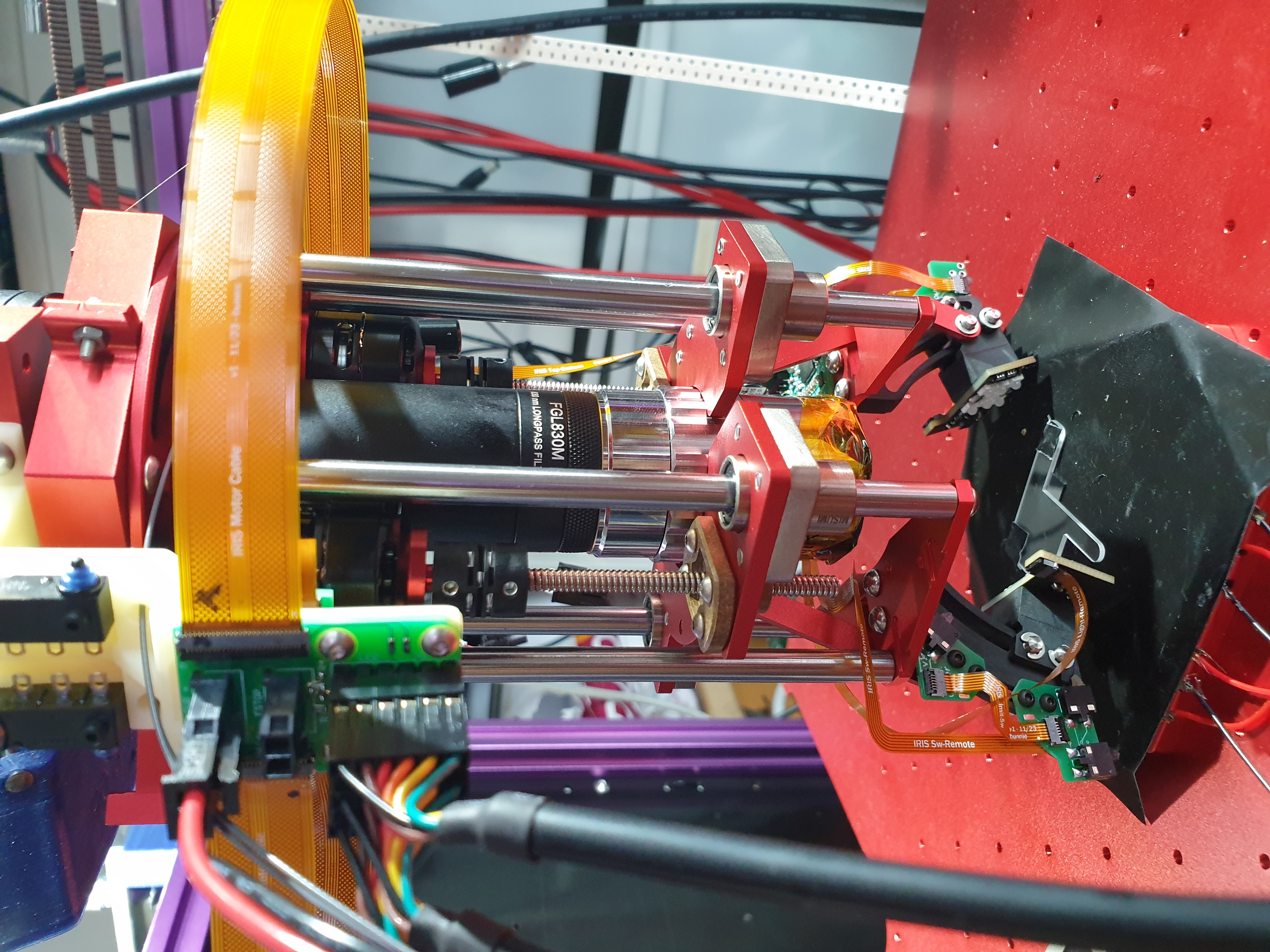
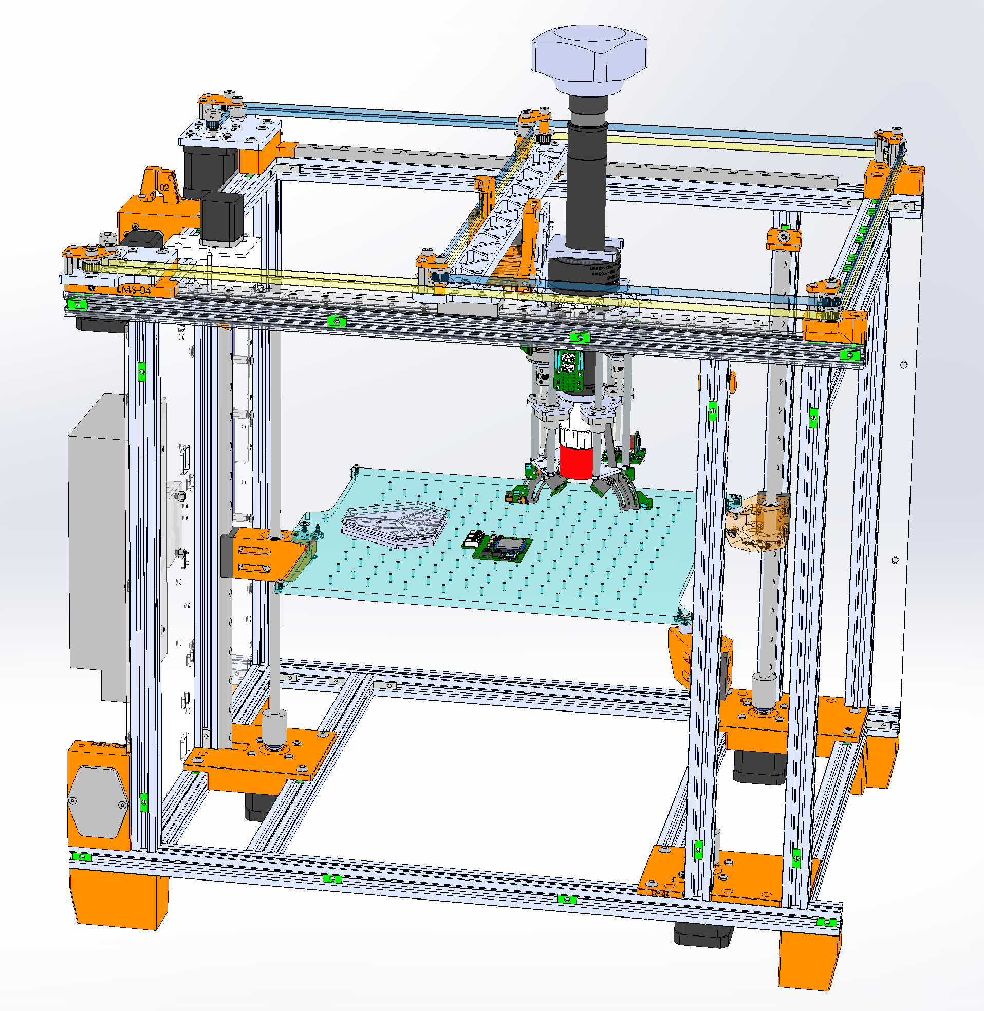
In my post about designing the light source for IRIS, I covered the electronic design, and noted that an important conclusion of the electronic design exploration was the need for a continuously variable, 2-axis mechanical positioning solution for the light sources. This post dives into the details of the mechanical positioning solution, shown above.
Background
Early experiments with IRIS revealed that what you could see on a chip depended heavily upon the incident angle of the light:
Initially, I tried to do the angular positioning entirely using an electronically addressable strip of LEDs, but the pixel density was insufficient. So, I decided to bite the bullet and design a continuously adjustable mechanical solution for positioning the lights.
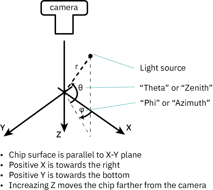
Above is the coordinate system used by IRIS. Framed in this context, what I wanted was the ability to adjust the theta/zenith and phi/azimuth of a directional, point-like light source. The distance of the light source to the sample would be nominally fixed, but the intensity can be varied electronically.
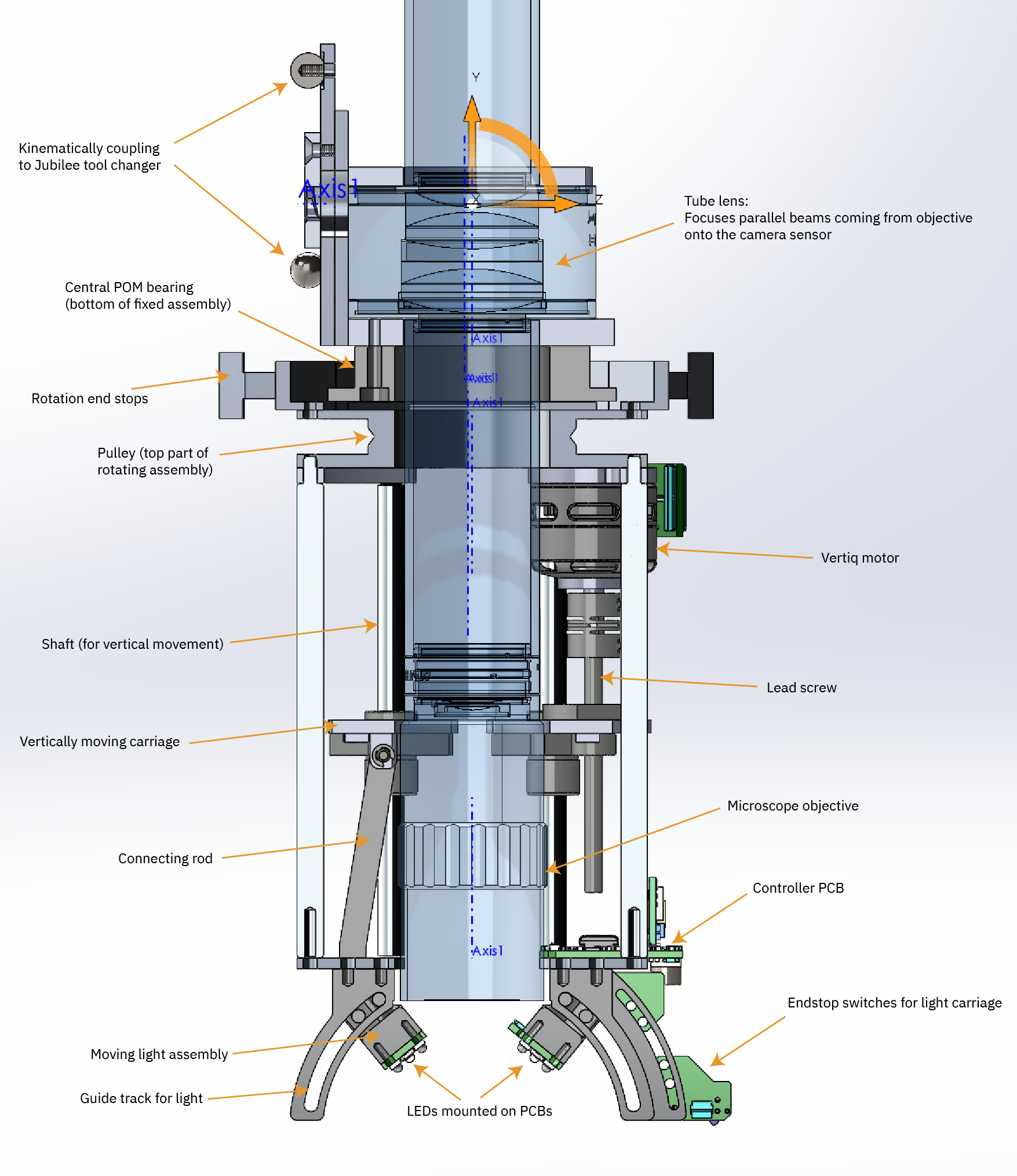
Above is a cross-section view of the final assembly. The microscope runs through the center, and is shaded blue and rendered transparently. Let’s walk through that design.
Zenith Control
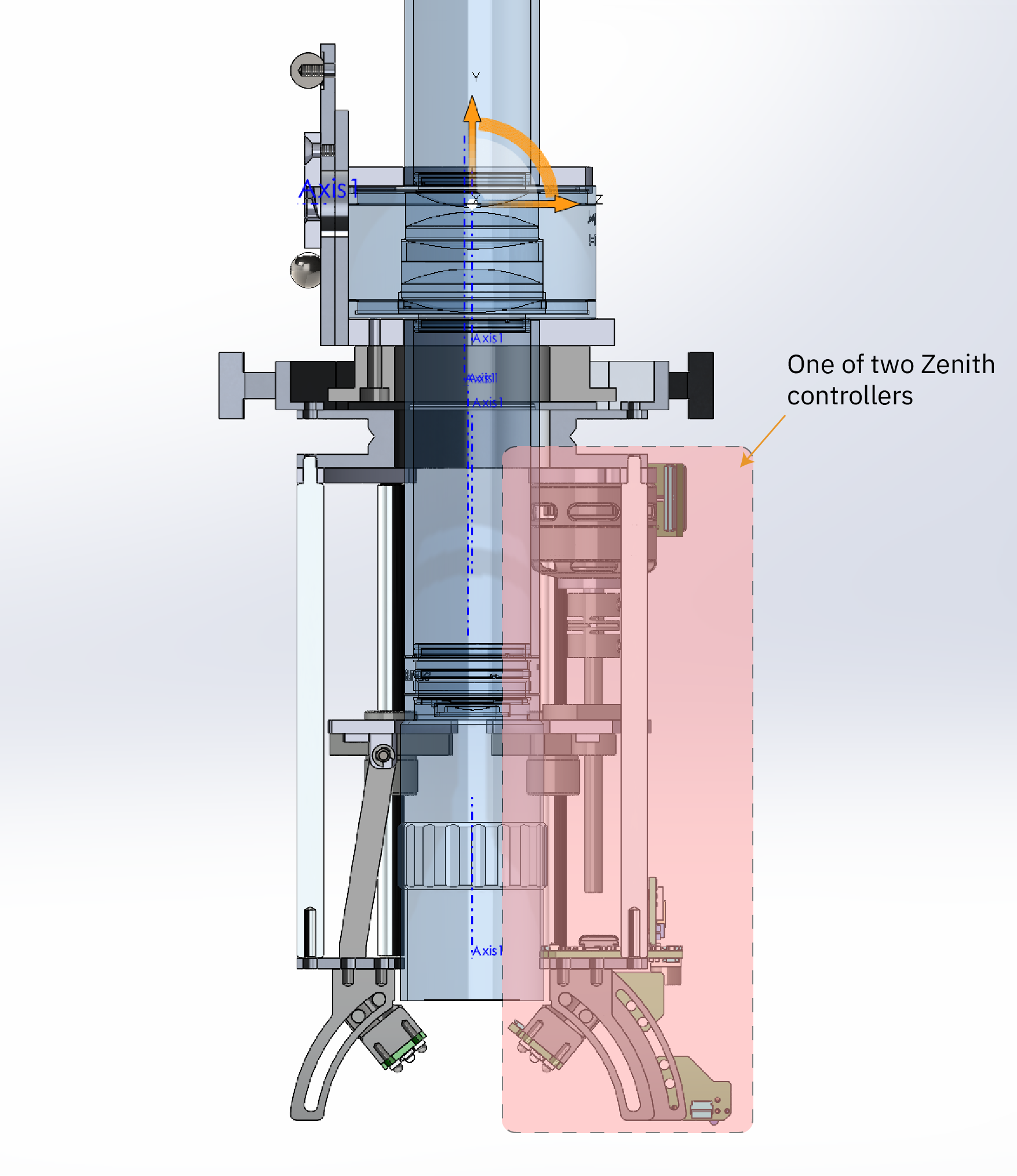
The zenith control sets how high the light is relative to the surface of the chip. It’s highlighted in the diagram above.
Zenith adjustment was conceptually straightforward: a lead screw would drive a connecting rod to the light source. The light source itself would be mounted on a shuttle that traveled along a mechanical track tracing a constant-radius arc about the focal point. This is a common mechanical design pattern, similar to a piston on a crank shaft, or other cam-and-follower idioms.
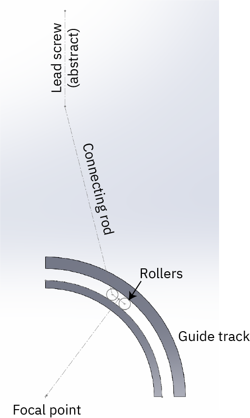
Above is an annotated screenshot of a quick motion study I did to make sure I wasn’t missing any crucial details in the execution of the design. This is done in Solidworks, using the dynamic mate solver to convince myself that the rollers will move in a fashion that can keep a PCB facing the focal point with a constant normal when the “lead screw” (abstractly modeled as just a centerline) is moved up and down.
Azimuth Control
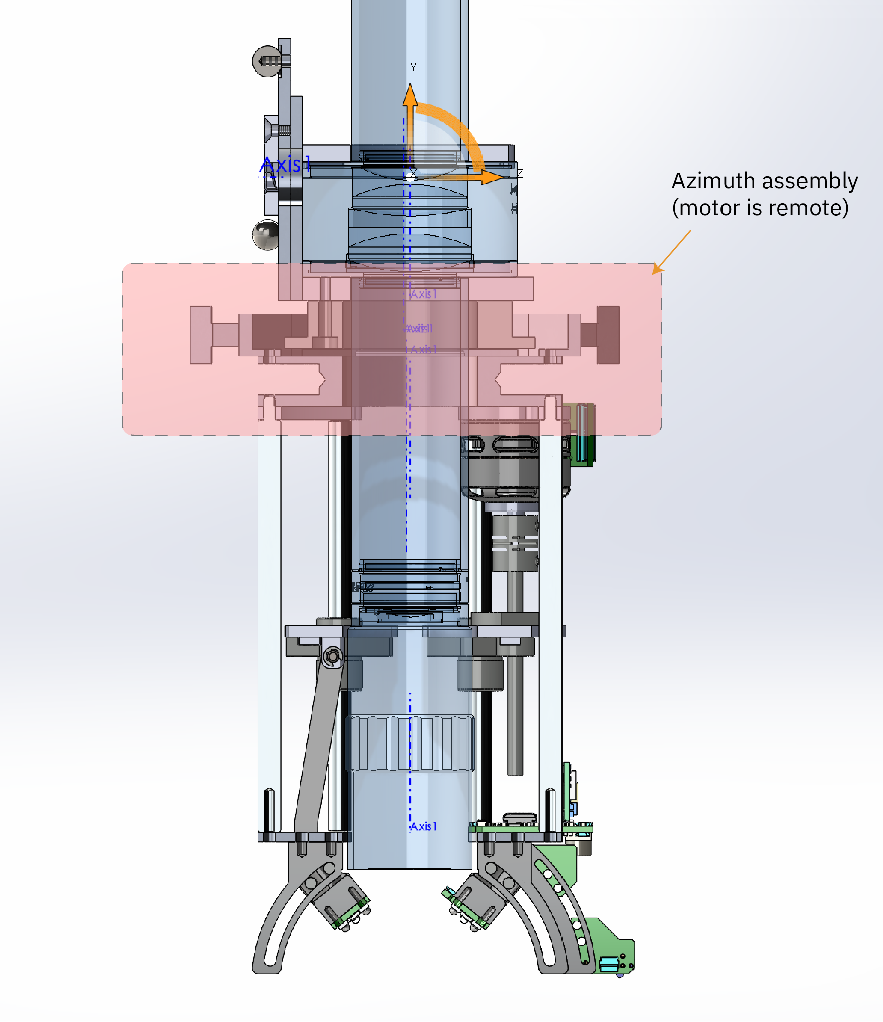
The azimuth control spins the lights around the axis that runs through the center of the microscope, and a portion of it is highlighted in the assembly above.
Designing the azimuthal adjustment mechanism was much more vexing than the zenith control, because the assembly had to coaxially rotate around a central, static microscope tube.
To get inspiration, I read a bunch of mechanical parts catalogs, and watched some YouTube videos of “satisfying and/or ingenious machines”. It turns out that coaxial motion around a central shaft containing precision components is not a terribly common design pattern. Some of the strategies I found included:
- A self-propelling carriage that runs over a static coaxial track (either through a circular rack-and-pinion or a frictional wheel on a smooth track surrounding the tube)
- A self-propelling carriage that engaged the axial surface of the microscope tube through frictional coupling of a wheel, or a belt wrapping around the tube (so imagine a thing that rolls directly on the tube itself, as opposed to a track surrounding the tube)
- A pulley driving an assembly mounted on a coaxial bearing large enough to accommodate the tube in its center
The first concept was the easiest to wrap my head around, because a small DC motor driving a carriage on a track is like building a small toy train that could drive around in circles. However, it required putting the motor mass in the moving assembly, and using a single motor to drive the carriage introduced concerns about asymmetries due to a lack of balance around the central axis. The second idea is quite similar to the first, but even harder to execute. For these reasons, I decided to pursue neither of the first two ideas.
The last idea, a pulley driving an assembly mounted on a coaxial bearing, had the advantage that I could re-use the Jubilee’s cable-driven pulley design for the tool changer (referred to as the “remote elastic lock”); so from that stand point, the motor, drive software, and coupling were already done and tested. It also moved the motor mass out of the moving carriage assembly, and lent itself to a symmetrically balanced arrangement of parts.
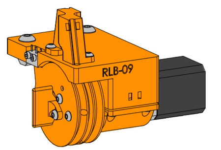
Above: rendering of the Jubilee remote elastic lock motor assembly.
The challenge of this approach is how to build a coaxial bearing for the outer moving assembly. The bearing is unusual in that the load is parallel to the axis, instead of perpendicular to it. Most bearings with a hole large enough to accommodate the microscope tube are designed for really big, powerful machines (think of a motor that has a 2.5cm (1 inch) drive shaft!), and are likewise big and heavy, and also not rated for loads parallel to the axis.
So, I had to guess my way through designing a bespoke bearing mechanism.
I figured the first step was to make the load as light as possible, without sacrificing precision. I decided for symmetry there would be two lights, so they would serve as counter-balances to each other. This also meant I could reduce the range of motion to a bit over 180 degrees, instead of 360 degrees, to get full coverage of the chip. However, this also doubled the weight of the mechanism.
Motors are the heaviest component, so to reduce weight I used a pair of Vertiq 23-06 2200KV position modules (distributor / datasheet). I had previously written about these, but in a nutshell they are BLDC motors, similar to the ones used in light-weight quadcopter drones, but with a built-in microcontroller, drive electronics and sensors that allowed them to act like stepper motors through some firmware changes. They are the smallest, lightest, and best power-to-weight ratio “serial to position” modules I am aware of, making them perfect for the zenith drive mechanism.
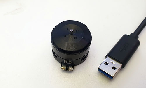
Above: Vertiq 23-06 2200KV position module, with USB connector for scale. It’s the smallest, lightest “serial-to-position” widget that I know of.
With the weight of the load thus fixed, I determined I could probably get away with building the bearing using three “cam follower” wheels – basically a ball bearing on a shaft – normally used for cam mechanisms. In this case, the “cam” is simply a flat, circular track made out of POM (for low friction and wear properties), and the “followers” are miniature cam followers available from Misumi. They are arranged around the central bearing using a hexagonal clamp composed of three identical parts that are screwed together to fully constrain the follower’s motion to stay on the circular path.
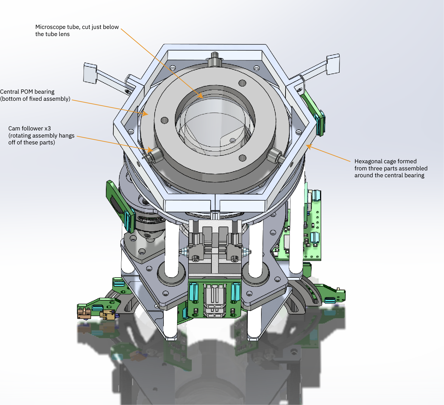
Above is a transverse cross-section view of the assembly, where the section plane cuts just below the tube lens, allowing us to clearly see the central bearing and three cam followers riding on it. As a reminder, you can click on any of the images in this post and get a larger version, to make the label text more legible.
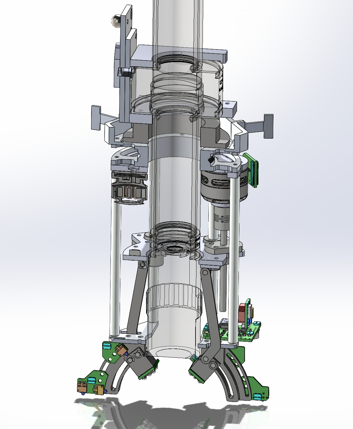
Above is a section view similar to the first section view, but slightly tilted and with the section plane adjusted so that you have full view of both of the lighting assemblies, located near the bottom of the image.
The rotating assembly is driven by a pulley that is coupled by cables to a stepper motor mounted on the Jubilee chassis – as mentioned above, the drive is just a copy of the existing mechanism included on the Jubilee for actuating the tool changer, down to using the exact same cables, cable guides, and stepper motor. The main difference is that the pulley is enlarged to match the size of the pulley on the rotating assembly, allowing the gearing ratio between the stepper motor and the rotating assembly to remain the same.
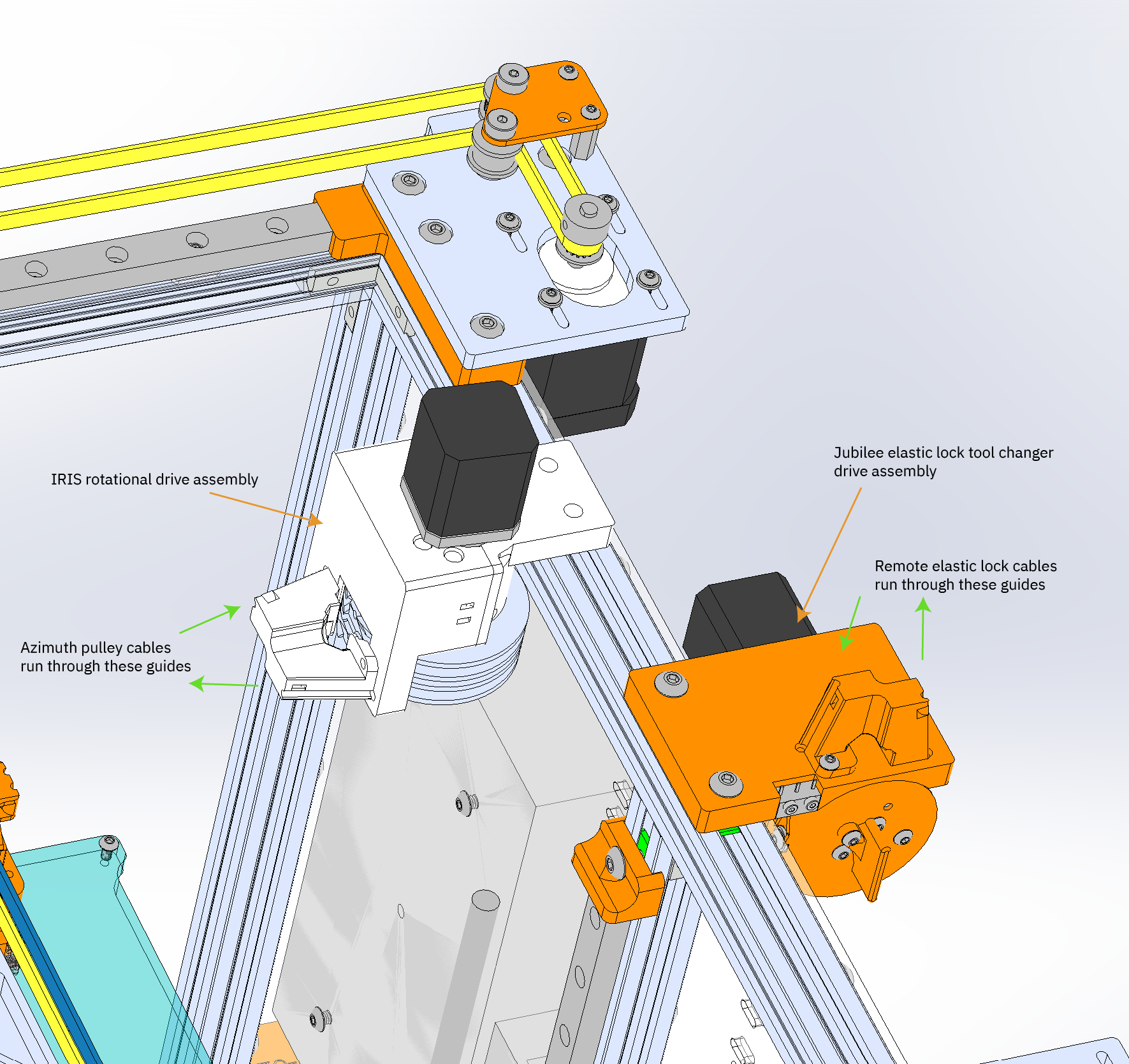
The rendering above shows the two drive mechanisms mounted on the chassis. Note that the cables and wires are not explicitly drawn in the rendering, but are indicated by the overlaid green arrows.
Putting It All Together
It’s so nice to have the design source for your motion platform. Jubilee is an open source science platform out of Prof. Nadya Peek’s Machine Agency Group (of which I am an affiliate), and all of the design files are available for editing. It’s nice that there are no barriers to copying their ideas and extending them – I can take the parts of the platform that I like and re-use them with ease.
Because I have the full design, I can also integrate my changes into their assembly and check that yes, in fact, everything fits as planned:
This sort of detailed modeling pays off, because so far I’ve not had to re-machine a part because it didn’t fit (knock on wood!).
One other thing I’d like to note about the Jubilee motion platform is that the assembly instructions are really thorough and clear. I have a lot of appreciation for the time and effort that went into preparing such comprehensive documentation.
I was able to build the platform on my first attempt in about two days, with little confusion or trouble. I’ve also mentioned this previously, but the Jubilee is available in kit form via Filastruder, as well as various spare parts and sub-assemblies. This was a big time saver, because when I copied the elastic lock toolchanger assembly to work as my rotational axis actuator, most of the tricky parts I could just order as spares from the Filastruder site.
The design file for all the parts shown in this post can be found in this repository. As with the fine focus stage, I had all the parts machined by Victor at Jiada; if you want copies of various pieces, and you have Wechat, you can contact him at “Victor-Jiada” and send along the corresponding CAD file. Just let him know that you got his contact via my blog.
In Action
Below is a loop demonstrating the mechanisms described in this post:
And below is a video of a region of a chip being imaged while the azimuth of the light is continuously varied:
I’m fairly pleased with the performance of the overall design, although, there are still some rough edges. The control software still has some minor bugs, especially when recovering from crashes when the actuators are already at an end-stop limit – I have to manually move the actuators off the end stop before the control software can function again. The focal point of the lights is also shifted by a couple of millimeters, due to a last-minute change in preferred microscope objectives. Fixing that should be pretty easy; I will need to remake the semi-circular tracks on which the lights travel, as well as the connecting rods to the lead screws to compensate for the change.
Going forward, I’m probably going to augment the design with a laser-based 1064nm light source. This turns out to be necessary for imaging chips with highly doped substrates. The transparency of silicon goes down quickly with dopant concentration. Foundries like TSMC seem to use a very lightly doped “P-” type of base wafer, so their chips image well at 1050nm. However, shops like Intel seem to use a heavily doped “P+” type of base wafer, and the wafers are much more opaque at that wavelength. I’m not 100% sure of the mechanism, but I think the extra dopant atoms scatter light readily, especially at shorter wavelengths. LED light sources have a fairly broad spectrum, so even if the center wavelength is at 1050nm, there’s a substantial amount of light still being emitted at 1000nm and shorter. These shorter wavelengths interact heavily with the dopant atoms, scattering in the bulk of the silicon.
Imaging chip built on a heavily doped substrate with an LED light source is like trying to see through thick fog with your high beams on: you see mostly a bright gray, with glints of the underlying wires coming through every now and then. A 1064 nm laser has a tighter bandwidth – just a couple of nm wide – and so the interaction with silicon substrate is more proportional to the light that’s reflected off of the wires underneath. It’s still a challenge to image chips with unthinned substrates, but early experiments seem promising, and I would like to be able to easily image Intel CPUs as part of the capabilities of IRIS.
The main downsides of using a laser for imaging are the cost (good quality lasers run a minimum of $100) and export controls (IR lasers are flagged by the US as requiring elevated scrutiny for export, and are thus harder to buy; incorporating it into the design transitively limits the market for IRIS). Lasers also interact strongly with sub-wavelength features on the chip, which is a plus and a minus; on the upside, there is more opportunity to gather information about the structure of the chip; on the downside, you have to be extremely precise in your laser’s positioning to make reproducible measurements. Also, credit where credit is due: I didn’t come up with the idea of using a laser for this, Cactus Duper has been independently exploring IRIS techniques, and showed me that lasers can cut through the fog of a heavily doped wafer substrate.
This post concludes my discussions about the mechanical and electrical design of the current iteration of the IRIS machine. The next couple of posts will touch on the control and analysis software I’ve written that compliments the IRIS hardware.
Again, a big thanks to NLnet and to my Github Sponsors for making this research possible!

Did you consider using movable mirrors or other reflectors instead of moving the light source? I don’t know a lot about this area, but it’s my understanding that’s the standard approach for pointing movable lasers. Given that you’re looking at using (transitioning to?) a laser, that seems an obvious choice, but perhaps it makes sense for more than just that?
Good question! I did consider mirrors and fiber optics. It turns out that the LED light source is so small, light and cheap, there’s almost no advantage to using mirrors (where you’d have to also deal with tolerances in mounting, losses in reflection, and cost). The “chunky” mounting for the LED lights was designed because the light source was in fact *too small*: I wanted the lights closer to the focal point, so I thickened the mounts with excess material to bring the LED PCB closer to the sample.
A laser light source is similarly small, modulo the necessary heat sink to keep its temperature in spec, but I’m able to fit it within the existing assembly dimensions.
A fiber optic would allow a more powerful laser to be used with extensive off-board cooling, but fiber-bonded lasers are over 10x more expensive than a raw laser diode (and the equipment I’d have to buy to align my own fibers didn’t look cheap). You also still need a collimator lens to focus the light coming out of the fiber optic. That lens is relatively large; so in the end, it was cheaper and easier to integrate the laser directly into the imaging head. This has the added benefit that as the assembly rotates over 180 degrees, you don’t have to worry about the bend radius of the fiber, or the fiber swinging around and getting snagged.
[…] 详情参考 […]
would using a ~1480nm pump laser work? (they seem fairly cheaply available with power output of 140mW to 600mW and attached fiber pigtail [sometimes connectorized])
Unfortunately that’s a bit outside the sensitivity range of the cheap CMOS sensors. Their efficiency drops off a cliff around 1100nm, almost nil by 1200nm.
This work reminded me of Polynomial Texture Mapping out of HP Labs circa 2001, likely long obsolete.
> Typically, PTMs are used for displaying the appearance of an object under varying lighting direction, and lu,lv specify the direction of a point light source. … PTMs are typically produced with a digital camera by photographing an object multiple times with lighting direction varying between images.
https://web.archive.org/web/20081022093357/http://www.hpl.hp.com/research/ptm/
I was wondering if this could be applicable to a laser communication terminal. The design looks very similar to what I’ve seen in that category.